
A scanning platform for imaging radiometer

A scanning platform, radiometer technology, applied in optical radiation measurement, radiation pyrometry, machine/stand and other directions, can solve the problem of inaccurate moving distance of the sliding table, and achieve the accurate moving process of the sliding table, eliminate jitter, and stabilize good effect

Active Publication Date: 2020-02-04
NANJING UNIV OF POSTS & TELECOMM +1
View PDF6 Cites 0 Cited by
  • Summary
  • Abstract
  • Description
  • Claims
  • Application Information

AI Technical Summary

Problems solved by technology

The invention solves the technical problem of inaccurate moving distance of the sliding table on the scanning platform

Method used


Image

  • A scanning platform for imaging radiometer
  • A scanning platform for imaging radiometer
  • A scanning platform for imaging radiometer

Examples


Embodiment Construction

[0045] The present invention will be further described in detail below in conjunction with the accompanying drawings, so that those skilled in the art can implement it with reference to the explanatory text.

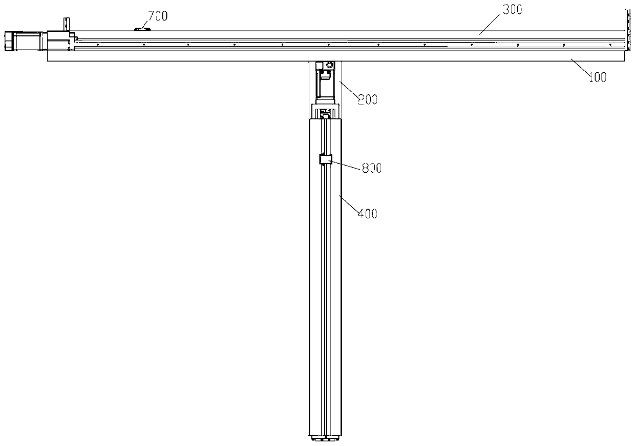
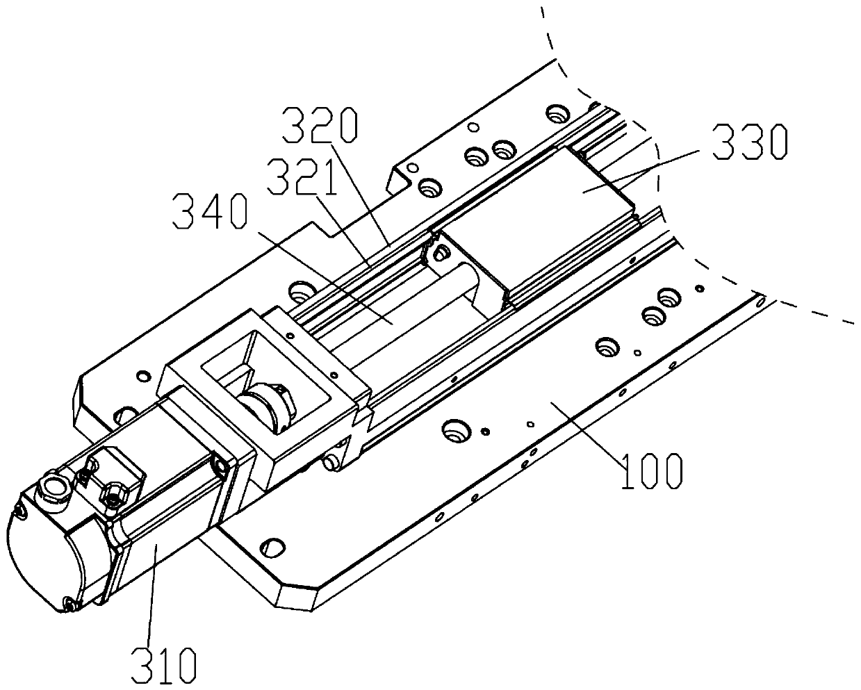
[0046] like Figure 1-9 As shown, the present invention provides a scanning platform for an imaging radiometer, including a bracket, a linear displacement mechanism, an oil pump and a control system.

[0047]Currently, the distributions of two-dimensional arrays used in imaging systems mainly include: "T"-shaped distribution, "ten"-shaped distribution, "U"-shaped distribution, "Y"-shaped distribution, circular distribution and other similar distributions. After simulating and analyzing the distribution of baselines (i.e. visibility sampling points) and point source imaging results (i.e. point spread function PSF) of the above several two-dimensional antenna arrays, it can be found that the "U" and "T" antenna arrays The distribution of array elements is similar, and the...


PUM


Abstract

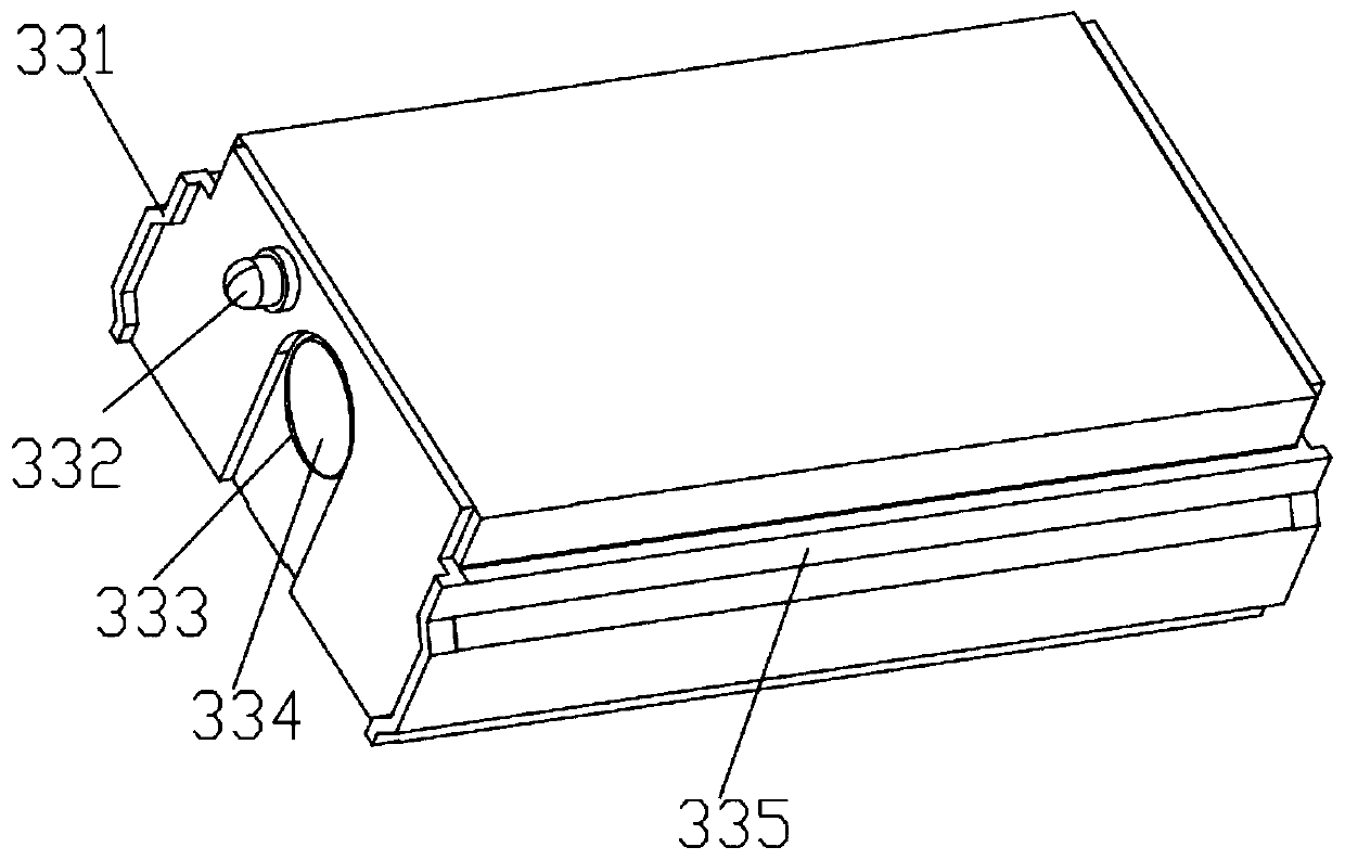
The invention discloses a scanning platform used for an imaging radiometer. The scanning platform used for the imaging radiometer comprises a T-shaped support, a first linear displacement mechanism, asecond linear displacement mechanism, an oil pump, a controller and an upper computer, wherein the oil pump communicates with the linear displacement mechanisms and an oil tank, the controller is connected with the linear displacement mechanisms and the oil pump, and the upper computer is in communication with the controller through a serial port and is provided with a display device. Each lineardisplacement mechanism comprises a driving mechanism, a first guide rail, a first sliding block, a second guide rail, a second sliding block, a third sliding block and a distance measurement module,wherein the first sliding block is slidably arranged in the first guide rail, the second guide rail is arranged at the upper end of the first guide rail, the second sliding block is slidably arrangedin the second guide rail, and the third sliding block is connected to the upper end of the second sliding block; and the oil pump communicates with the internal end space of the second guide rail through an electromagnetic valve, and a flowmeter is arranged on the electromagnetic valve. By adoption of the scanning platform used for the imaging radiometer, the technical problem that the moving distance of a sliding table on an existing scanning platform is inaccurate is solved.

Description

technical field [0001] The invention relates to the technical field of automatic control, in particular to a scanning platform for an imaging radiometer. Background technique [0002] The millimeter-wave synthetic aperture imaging radiometer, hereinafter referred to as the radiometer, uses an antenna array composed of small-aperture antennas to measure the millimeter-wave radiation signal of the target scene with high sensitivity, and measures the visibility function of the scene through the complex correlation calculation between the array elements, and Invert the brightness temperature distribution image of the target scene. Compared with the traditional real-aperture imaging technology, the comprehensive aperture imaging technology has the characteristics of good real-time performance and high spatial resolution. Imaging has been widely used in military, navigation, medical and traffic security inspection and other fields. The basic composition of the synthetic aperture...

Claims


Application Information

Patent Timeline
Patent Type & Authority Patents(China)
IPC IPC(8): G01J5/02F16M11/04F16M11/18F16M11/22
CPCF16M11/043F16M11/18F16M11/22G01J5/0205G01J2005/0077
Inventor 陈建飞张胜蔡志匡
Owner NANJING UNIV OF POSTS & TELECOMM
Learn More