Waste heat energy supply devices for distributed type cloud computing system
A technology of distributed cloud computing and equipment, applied in the field of waste heat recovery, can solve problems such as waste of thermal energy resources and environmental pollution, and achieve the effects of high reliability, flexible system operation, and significant waste heat recovery effect.
- Summary
- Abstract
- Description
- Claims
- Application Information
AI Technical Summary
Problems solved by technology
Method used
Image

Examples
Embodiment ( 1
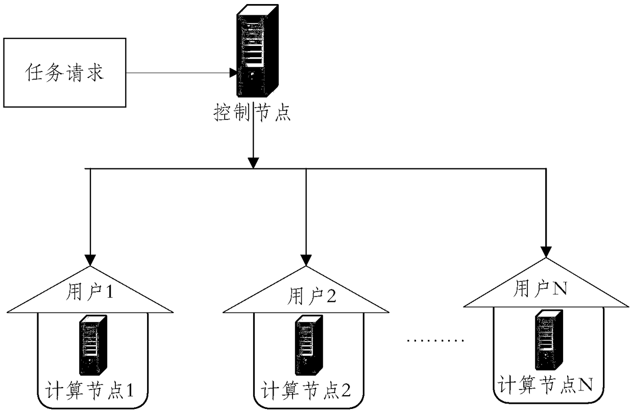
[0063] Such as figure 1 As shown, a distributed cloud computing system, the cloud computing system includes a control server and sub-services controlled by the control server, the sub-services are divided into groups, and each group is used as a computing node;
[0064] In the specific implementation process, the servers of the cloud computing system can be divided into N groups, and each group of servers as computing nodes is respectively set in N user families, and the number of groups specified in particular is only for illustration, and the present invention does not implement them. limited.
[0065] The server corresponding to the control node and the computing node interacts with each other. In this embodiment, the control node and the computing node are connected through a network. The server located in the heating user's home as a computing node can respond to the control node located in the data center, and the control node can distribute tasks to the computing nodes...
Embodiment ( 2
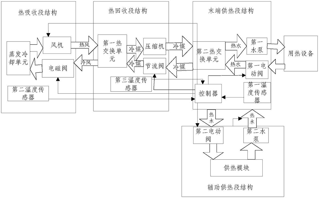
[0098] In the specific installation process, according to the different needs of household users for heating devices, on the basis of embodiment (1), the equipment of the present invention is also provided with an auxiliary heating section structure, wherein the auxiliary heating section structure includes: for A heating module that generates hot water, used to drive the water of the heating module into the second water pump of the third circulation channel, and used to control the opening or closing of the connection between the heating module and the third circulation channel The second electric valve, that is, the structure of the auxiliary heating section is used to meet the water demand of the user, and the structure of the auxiliary heating section supplies hot water to the third circulation channel to meet the needs of the user;
[0099] In the specific implementation process, the controller is used to control the heat exchange between the heat absorption section structu...
Embodiment ( 3
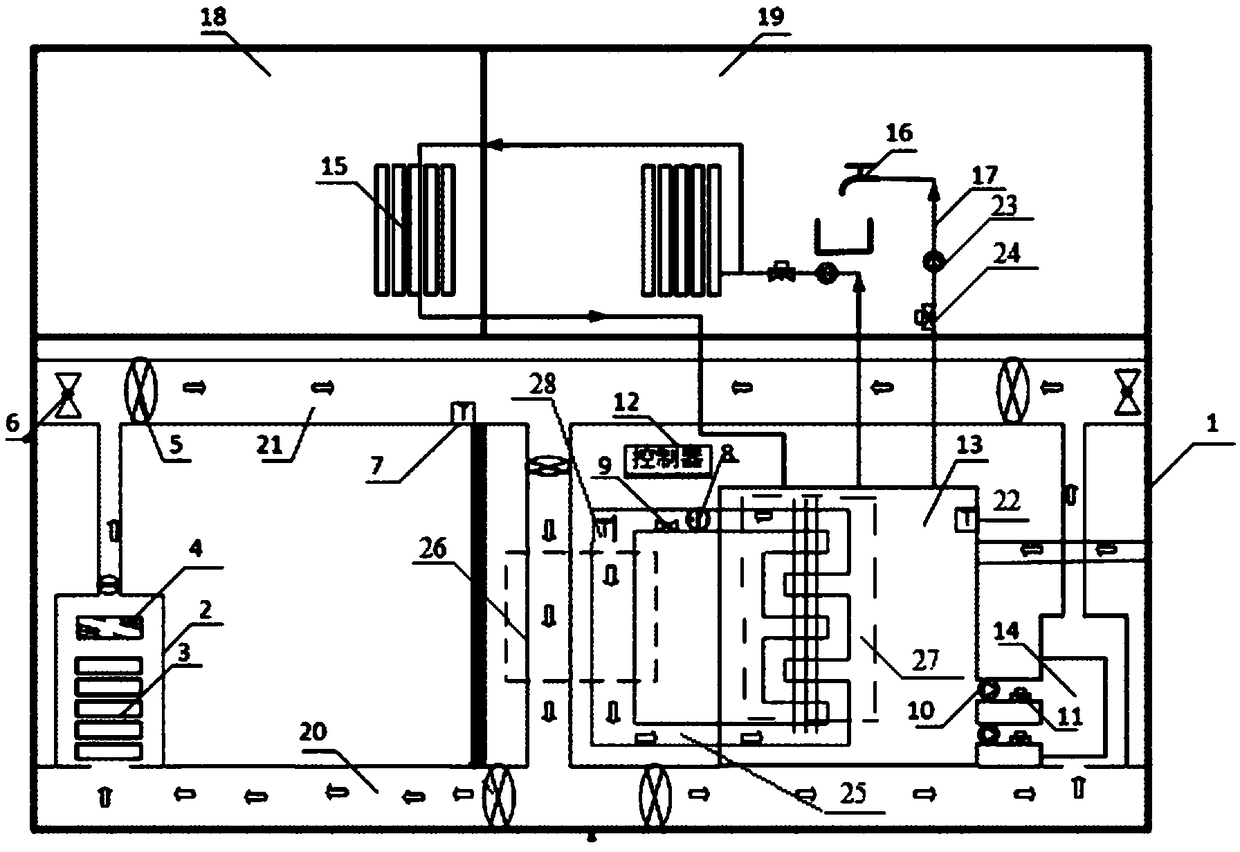
[0103] In this embodiment, the user family where the computing node of any cloud computing system is located is taken as an example, such as image 3 As shown, the specific structure of this embodiment is as follows:
[0104] The computing node 3 is set in the heating room 1 of the user's home, the evaporative cooling unit 4 is located above the computing node, and the fan 5 is set above the computing node. In this embodiment, the first circulation channel 2 is divided into two parts, and the upper part of the computing node is The direction close to the fan is recorded as the return air area 21, and the direction below the computing node away from the fan is recorded as the air supply area 20, the first temperature sensor 7 is set in the return air area, and the solenoid valve 6 is set on the side of the return air area;
[0105] In the specific implementation process, a plurality of fans are arranged in the air supply area and the air return area, and setting a plurality of ...
PUM
 Abstract
Description
Claims
Application Information
 - R&D
- Intellectual Property
- Life Sciences
- Materials
- Tech Scout
- Unparalleled Data Quality
- Higher Quality Content
- 60% Fewer Hallucinations
Browse by: Latest US Patents, China's latest patents, Technical Efficacy Thesaurus, Application Domain, Technology Topic, Popular Technical Reports.
© 2025 PatSnap. All rights reserved.Legal|Privacy policy|Modern Slavery Act Transparency Statement|Sitemap|About US| Contact US: help@patsnap.com