Fatigue crack growth rate measurement method based on infrared thermal imaging technology

A technology of fatigue crack growth and crack growth rate, which is applied in the direction of applying repetitive force/pulse force to test the strength of materials, etc., can solve the problems of high consumption of broken pieces, can not be reused, and increase the test cost, so as to save labor costs and reduce Human error, low test environment requirements

Active Publication Date: 2018-11-06
HUNAN UNIV
View PDF8 Cites 13 Cited by
  • Summary
  • Abstract
  • Description
  • Claims
  • Application Information

AI Technical Summary

Problems solved by technology

This method can realize automatic detection, but the disadvantage is that it cannot be reused, so the consumption of fracture pieces in the fatigue test is more, and the test cost is correspondingly increased

Method used


Image

  • Fatigue crack growth rate measurement method based on infrared thermal imaging technology
  • Fatigue crack growth rate measurement method based on infrared thermal imaging technology
  • Fatigue crack growth rate measurement method based on infrared thermal imaging technology

Examples


specific Embodiment approach

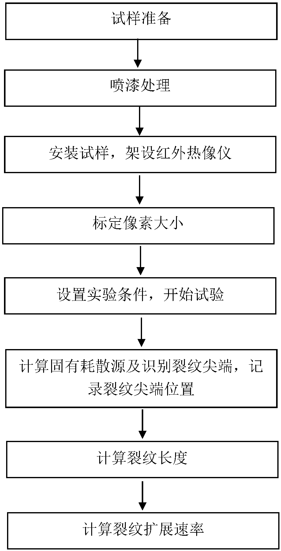
[0042] Below in conjunction with the operation flow chart, the specific implementation is described in detail as follows:

[0043] Sample preparation, painting treatment. The sample is machined to achieve the required geometry and surface roughness. Spray a thin and uniform layer of black matte paint on the surface of the sample to increase the thermal emissivity of the sample and ensure the uniform distribution of the surface emissivity.

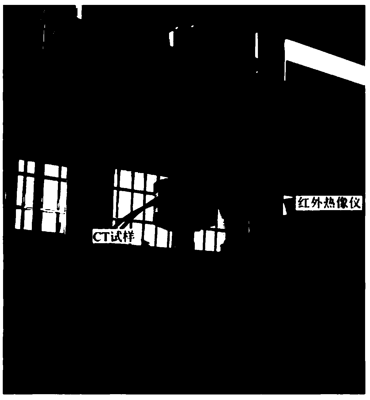
[0044] Install the sample and set up the infrared thermal imager. Before the experiment, try to ensure that the external environment is at a constant temperature, such as using an air conditioner for temperature control, so as to avoid the influence and interference of the ambient temperature fluctuation on the temperature field of the sample surface. Install the sample with a suitable fixture, set up the infrared thermal imager to a suitable position, adjust the focal length of the lens until the fatigue crack outline can be clearly obse...


PUM


Abstract

The invention discloses a fatigue crack growth rate measurement method based on infrared thermal imaging technology, including the following steps: spraying a black flat lacquer on a sample satisfyinga required geometric size and surface roughness to improve the surface emissivity of the sample; installing the sample, setting up an infrared thermal imager, determining an observation area, and calibrating the spatial resolution of an infrared image; setting fatigue loading parameters and infrared thermal imager sampling parameters, starting the fatigue test, and recording the temperature fieldevolution process in a fatigue crack tip region in real time; acquiring a corresponding heat source field through temperature field calculation with a two-dimensional heat transfer model, and automatically identifying the fatigue crack tip position in the heat source field; according to the change of the fatigue crack tip position, determining a crack propagation path, acquiring the fatigue cracklength at each moment, and calculating to obtain the fatigue crack growth rate. The method can be used to obtain accurate and reliable measuring results, has low requirements on test environment, iseasy to operate, and can realize non-contact measurement, full field measurement and automatic measurement.

Description

technical field [0001] The invention relates to the field of fatigue testing, in particular to a method for measuring fatigue crack growth rate based on infrared thermal imaging technology. Background technique [0002] In engineering practice, the service conditions of most engineering materials and structures are alternating loads, so they face the risk of fatigue failure. According to the fatigue and fracture theory, the fatigue crack size and crack growth rate on the surface of the service structure are important parameters for structural fatigue damage assessment and remaining fatigue life prediction. In order to avoid premature fatigue fracture failure of cracked structures during service, it is necessary to measure the length of fatigue cracks in time and accurately, and calculate the corresponding fatigue crack growth rate, so as to determine the inspection cycle of equipment and ensure its service performance and reliability. [0003] At present, a variety of meth...

Claims


Application Information

Patent Timeline
Patent Type & Authority Applications(China)
IPC IPC(8): G01N3/38
CPCG01N3/38
Inventor 王晓钢姜潮冉红瑞
Owner HUNAN UNIV
Why Eureka
Try Eureka