
Laser scattering oil fume monitor

A laser scattering and monitoring instrument technology, applied in the measurement of scattering characteristics, etc., can solve the problem of unstable light intensity, achieve the effect of strong anti-pollution ability, ensure accuracy, and improve service life

Active Publication Date: 2018-11-06
SHENZHEN TIANDEYI ENVIRONMENT TECH
View PDF23 Cites 3 Cited by
  • Summary
  • Abstract
  • Description
  • Claims
  • Application Information

AI Technical Summary

Problems solved by technology

[0005] The main purpose of the present invention is to provide a laser scattering oil fume monitor to solve the problem of unstable light intensity of ordinary lasers when measuring oil fume concentration

Method used


Image

  • Laser scattering oil fume monitor
  • Laser scattering oil fume monitor

Examples


Embodiment Construction

[0034] It should be understood that the specific embodiments described here are only used to explain the present invention, not to limit the present invention.

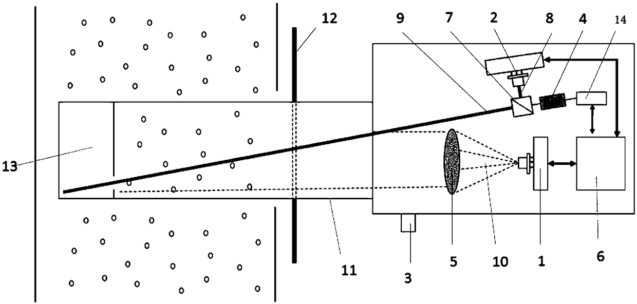
[0035] refer to figure 1 , the embodiment of the present invention proposes a laser scattering fume monitor, including a fuselage, a laser light source 4, a beam splitter 7, a first light receiver, a second light receiver 2, and an output processor 6 are arranged inside the fuselage;

[0036] Laser light source 4, used to emit laser beams;

[0037] The beam splitter 7 is used to divide the laser beam into a detection beam 9 and a correction beam 8. One end of the fuselage has an opening. When the monitor is working, the detection beam 9 is emitted from the opening;

[0038] The first light receiver is used to receive the scattered light 10 and convert the scattered light 10 into a first electrical signal, the scattered light 10 is formed by the detection beam 9 irradiating the oil fume in the exhaust pipe;

[0039] ...


PUM

PropertyMeasurementUnit
Apertureaaaaaaaaaa
Transmit poweraaaaaaaaaa

Abstract

The invention provides a laser scattering oil fume monitor. A laser beam is split into a detection beam and a correction beam through a beam splitter. The detection beam is used for detecting the oilfume concentration. The correction beam is used for correcting the intensity of the light source. A detection part of the laser scattering oil fume monitor is installed outside a smoke discharge pipeso that the influence caused by high temperature and high humidity oil fume substances in the smoke discharge pipe is avoided and the service life of a sensor is prolonged. The laser scattering oil fume monitor is less affected by the site environment and has the strong anti-pollution capability and a self-correction function. The dual optical path system can self-correct the light intensity fluctuation of the light source caused by environmental change and ensure the accuracy of the detection results.

Description

technical field [0001] The invention relates to the field of oil fume monitoring, in particular to a laser scattering oil fume monitor. Background technique [0002] With the rapid development of the catering industry, the problem of oil fume pollution has become increasingly prominent and has become one of the hot spots of environmental complaints. Routine monitoring of oil fume pollution in the catering industry has also received more and more attention from the industry. [0003] Because cooking fume is emitted intermittently, the concentration is high and low at times, and the traditional detection method has high requirements for on-site testing conditions, and the samples need to be brought back to the laboratory for analysis, and the detection cycle is long. Therefore, it has become a top priority to seek a rapid and real-time detection method suitable for cooking fumes in the catering industry. At present, the common oil fume detectors installed at the discharge si...

Claims


Application Information

Patent Timeline
IPC IPC(8): G01N21/53
CPCG01N21/53
Inventor 张汉辉白杨
Owner SHENZHEN TIANDEYI ENVIRONMENT TECH
Learn More