
Sensor applied to scanning probe microscope

A technology for scanning probes and sensors, applied in the field of scanning probe microscopes, which can solve problems such as sensor vibration, and achieve the effects of high quality factor, improved resolution and application range, and simple structure

Active Publication Date: 2018-11-06
SANMING UNIV
View PDF8 Cites 0 Cited by
  • Summary
  • Abstract
  • Description
  • Claims
  • Application Information

AI Technical Summary

Problems solved by technology

[0003] The technical problem to be solved by the present invention is to provide a sensor applied to a scanning probe microscope to solve the problem that the existing sensor can only vibrate in one dimension when scanning a sample

Method used


Image

  • Sensor applied to scanning probe microscope
  • Sensor applied to scanning probe microscope

Examples


Embodiment Construction

[0020] In order to make the purposes, technical solutions and advantages of the embodiments of the present invention clearer, the technical solutions in the embodiments of the present invention will be clearly and completely described below with reference to the accompanying drawings in the embodiments of the present invention. Obviously, the described embodiments These are some embodiments of the present invention, but not all of them. Based on the embodiments of the present invention, all other embodiments obtained by those of ordinary skill in the art without creative efforts shall fall within the protection scope of the present invention.

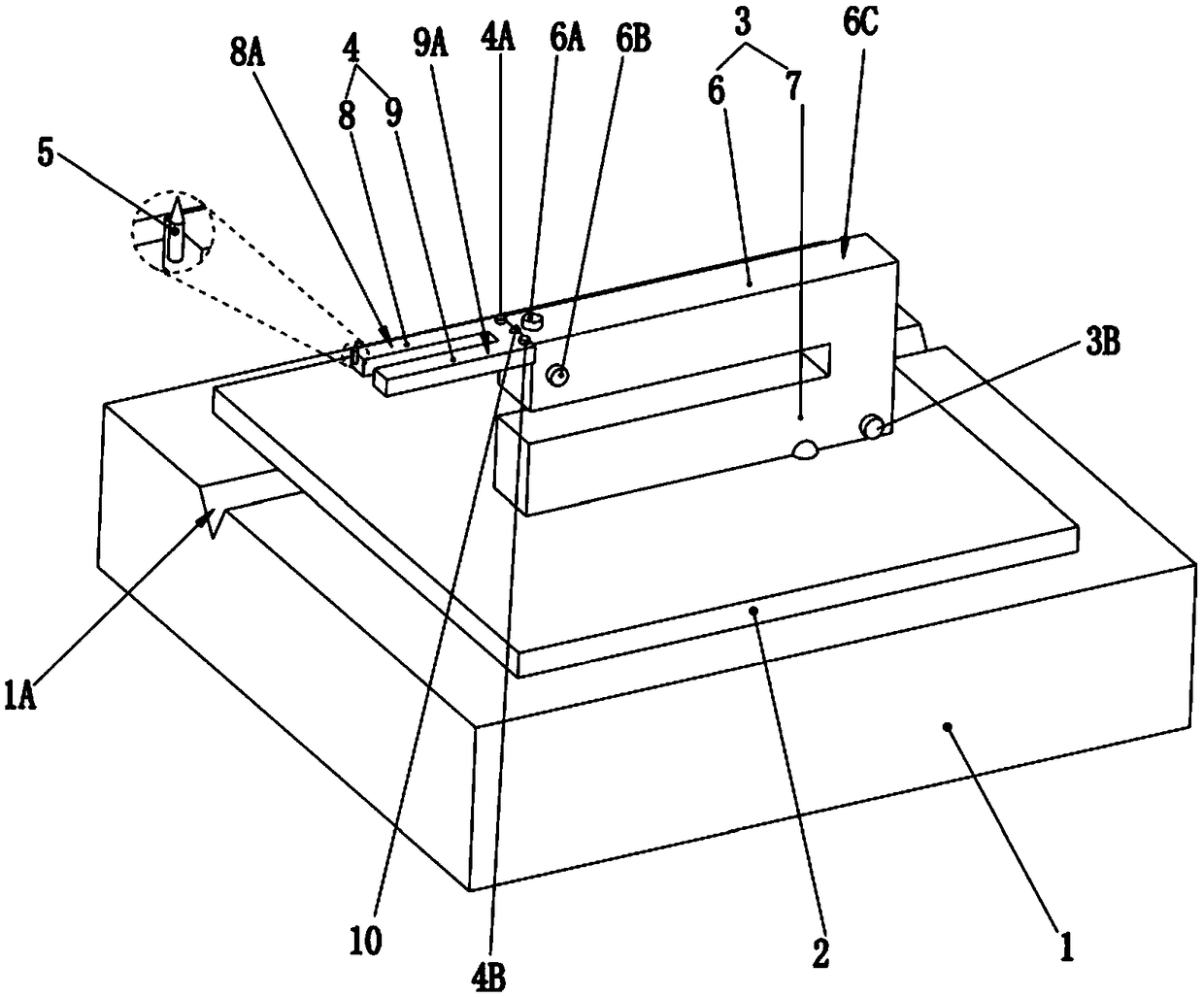
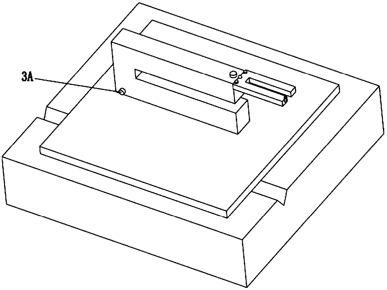
[0021] combine figure 1 and figure 2 , in one embodiment, the present invention is applied to a sensor of a scanning probe microscope, comprising: a base 1, an insulating carrier layer 2 located on the upper side of the base 1, a first quartz crystal oscillator 3 located on the insulating carrier layer 2, a second quartz crystal The ...


PUM

PropertyMeasurementUnit
Depthaaaaaaaaaa
Widthaaaaaaaaaa
Diameteraaaaaaaaaa

Abstract

The invention provides a sensor applied to a scanning probe microscope. The sensor comprises a base, an insulating bearing layer which is arranged on the upper side of the base, and a first quartz crystal oscillator, a second quartz crystal oscillator and a probe which are arranged on the insulating bearing layer. The first fork pin of the first quartz crystal oscillator and the second fork pin ofthe first quartz crystal oscillator are vertically and oppositely configured. The first fork pin of the second quartz crystal oscillator and the second fork pin of the second quartz crystal oscillator are oppositely configured in a left-and-right direction. The base part of the second quartz crystal oscillator is configured on the first fork pin of the first quartz crystal oscillator. The probe is configured on the first fork pin of the second quartz crystal oscillator. All the fork pins of the first quartz crystal oscillator and the second quartz crystal oscillator are identical in extensiondirection and the resonant frequency is different. The sensor has the advantage of simple structure, and the sensor has the two-dimensional in-situ excitation / detection function.

Description

technical field [0001] The present invention relates to scanning probe microscope technology, in particular, to a sensor applied to scanning probe microscope. Background technique [0002] Scanning probe microscope is a general term for all microscopes that mechanically scan and move the probe on the sample to detect the image of the sample, mainly including atomic force microscope, laser force microscope, magnetic force microscope, etc. At present, scanning probe microscopes used for scientific research and commercial production mostly use micro-cantilever tip-integrated sensors, which can obtain information on the surface of materials. Specifically, when the scanning probe is working, the micro-cantilever tip approaches the sample surface from top to bottom along the vertical direction (counted as the Z direction), and after approaching the sample surface, it moves vertically or horizontally (counted as the X direction). ) relative to the sample surface to scan the sample...

Claims


Application Information

Patent Timeline
IPC IPC(8): G01Q60/00
CPCG01Q60/00
Inventor 彭平兰永强
Owner SANMING UNIV
Learn More