Sensor for current detection based on new energy automobile inverter
A new energy vehicle and current detection technology, applied in the direction of measuring current/voltage, instruments, measuring devices, etc., can solve the problem of meeting the needs of new energy vehicle inverter current detection products with high current, small size, high reliability and low cost detection and other issues, to achieve the effect of improving product environmental reliability, high-precision detection, and small size
- Summary
- Abstract
- Description
- Claims
- Application Information
AI Technical Summary
Problems solved by technology
Method used
Image
Examples
Embodiment 1
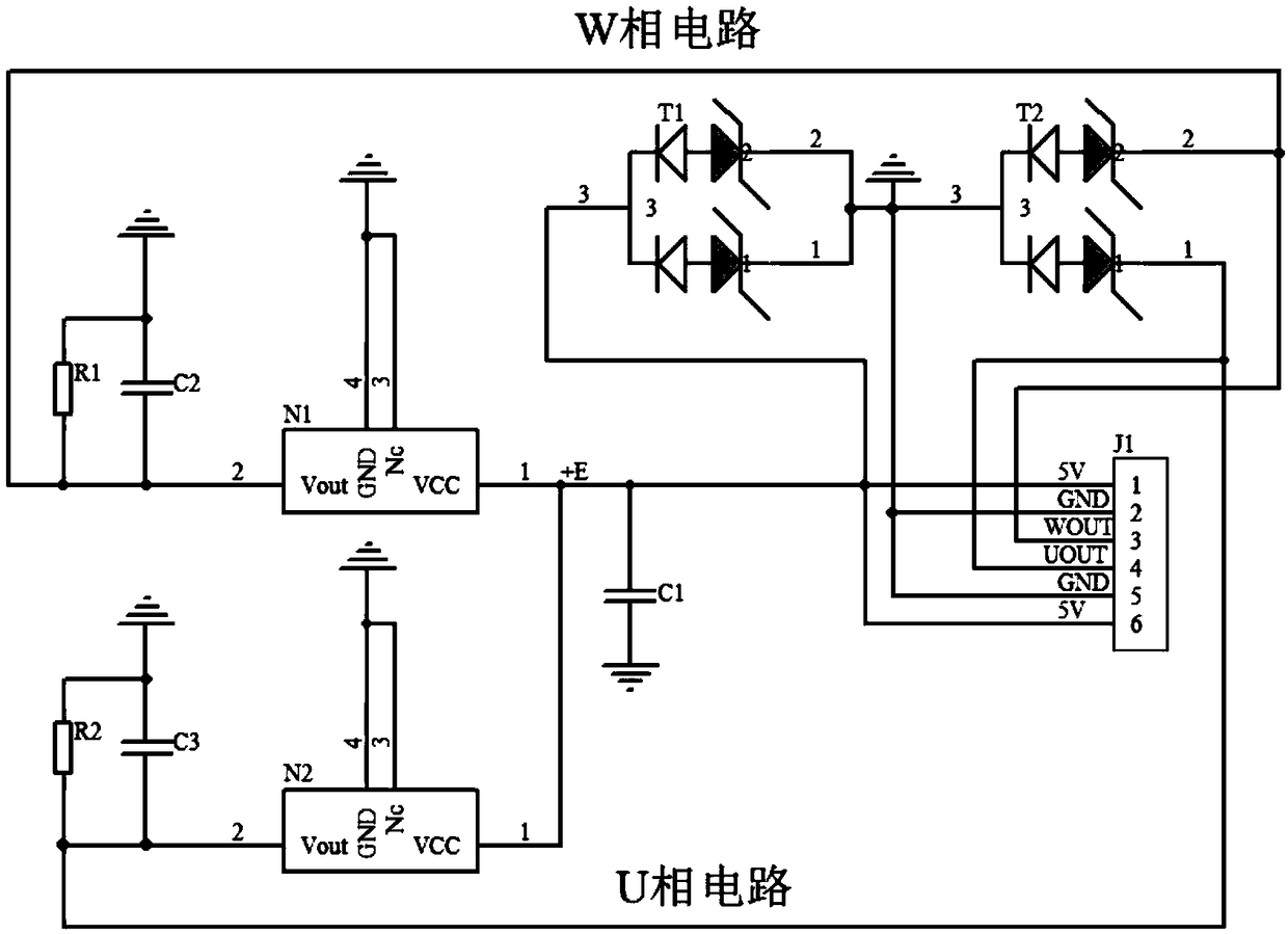
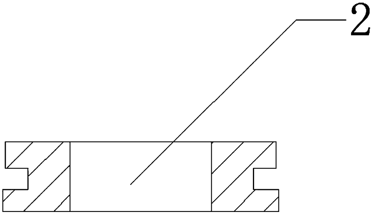
[0025] Such as Figure 1~4 As shown, the present invention is based on a new energy vehicle inverter current detection sensor, which can be used for high reliability and fast measurement in the case of small volume, high current and continuous power supply. It can detect two channels of measured current signals, and each channel includes a magnetic circuit and a measurement circuit. The magnetic circuit includes a ring core 1 to convert the measured current into a magnetic field; the measurement circuit includes a Hall element and its peripheral circuit. The component is centered and vertically placed in the center of the opening of the ring magnetic core 1, and the measured magnetic field is converted into a Hall potential output by using the principle of the Hall effect. By detecting the output Hall voltage, it can indirectly reflect the magnitude of the measured input current.
[0026] Specifically, in order to improve product reliability and reduce product volume, the Hal...
Embodiment 2
[0028] Such as figure 1 , Figure 4 As shown, this embodiment is optimized on the basis of Embodiment 1. J1 is a dedicated automotive-grade plug-in terminal for providing power and output interfaces; T1 / T2 are bidirectional TVS diodes for EMC protection of power and output terminals ; N1 / N2 is an integrated Hall IC, which converts the magnetic field detected by the ring core 1 into a Hall potential output, and the pin 3 of the Hall IC is grounded to improve the ESD protection capability; C1 is used to power the Hall IC chip VCC Perform decoupling filtering; C2 / C3 / R1 / R2 are used for Hall potential output filtering. Toroidal core 1 in figure 1 Not reflected in location.
[0029] The sensor is powered by a low-voltage single power supply of 5V, and the static power consumption of the product is determined by the Hall IC, generally 10mA. Hall IC sensitivity K N The gear selection is determined by the ring magnetic core 1 opening l, the output specification V 0 and the measur...
Embodiment 3
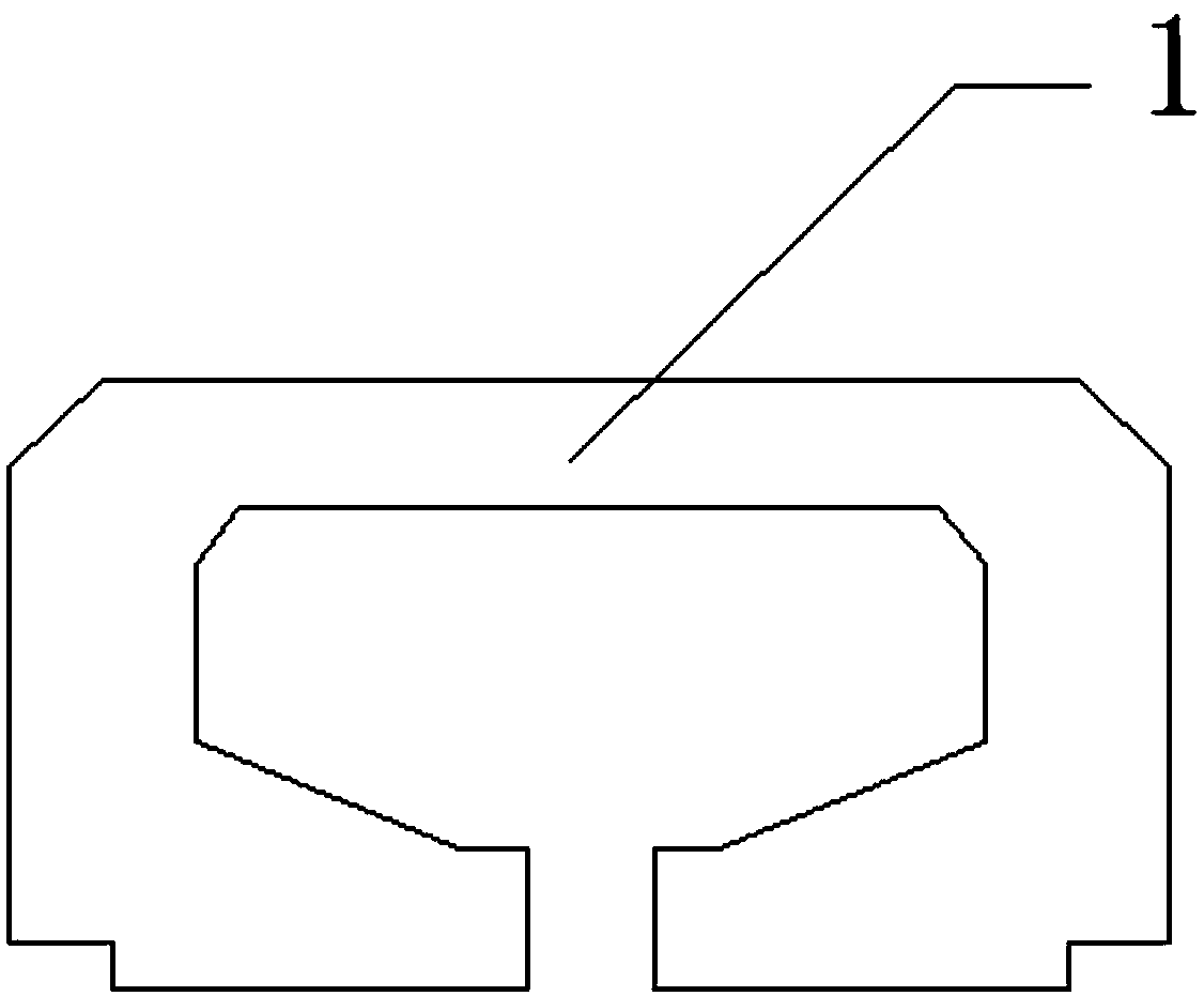
[0031] Such as figure 2 As shown, this embodiment has been optimized on the basis of the above-mentioned embodiments, and the external dimensions of the ring magnetic core 1 are shown in figure 2 shown. Ring magnetic core 1 selects silicon steel strip with high saturation magnetic induction intensity, low loss, and low coercive force, and the opening of ring magnetic core 1 is determined by the measured current size I 0 And the saturation magnetic induction intensity Br of the magnetic material is determined. The annular magnetic core 1 is processed by die, which can improve the batch consistency of the product and reduce the product cost. The position and size of the stacked riveting are not marked in the figure.
[0032] The annular magnetic core 1 is fixed by injection molding into the casing. The thickness of the injection molding plastic is not less than 0.8mm. It is recommended to choose PV66+30% GF or PBT+30% GF for the plastic to achieve normal use in the environm...
PUM
 Abstract
Description
Claims
Application Information
 - R&D
- Intellectual Property
- Life Sciences
- Materials
- Tech Scout
- Unparalleled Data Quality
- Higher Quality Content
- 60% Fewer Hallucinations
Browse by: Latest US Patents, China's latest patents, Technical Efficacy Thesaurus, Application Domain, Technology Topic, Popular Technical Reports.
© 2025 PatSnap. All rights reserved.Legal|Privacy policy|Modern Slavery Act Transparency Statement|Sitemap|About US| Contact US: help@patsnap.com


