
Thin-film low resistor and L-type resistor adjusting method therefor

A thin-film and L-shaped technology, which is applied in thin-film resistors, resistors, resistor manufacturing, etc., can solve the problems of thin-film low-resistance adjustment and low precision

Active Publication Date: 2018-11-06
CHINA ZHENHUA GRP YUNKE ELECTRONICS
View PDF3 Cites 0 Cited by
  • Summary
  • Abstract
  • Description
  • Claims
  • Application Information

AI Technical Summary

Problems solved by technology

[0004] The purpose of the present invention is to provide a thin film low resistance and a thin film low resistance L-type resistance adjustment method, which solves the problem of low accuracy of thin film low resistance adjustment resistance in the prior art

Method used


Image

  • Thin-film low resistor and L-type resistor adjusting method therefor
  • Thin-film low resistor and L-type resistor adjusting method therefor

Examples


Embodiment

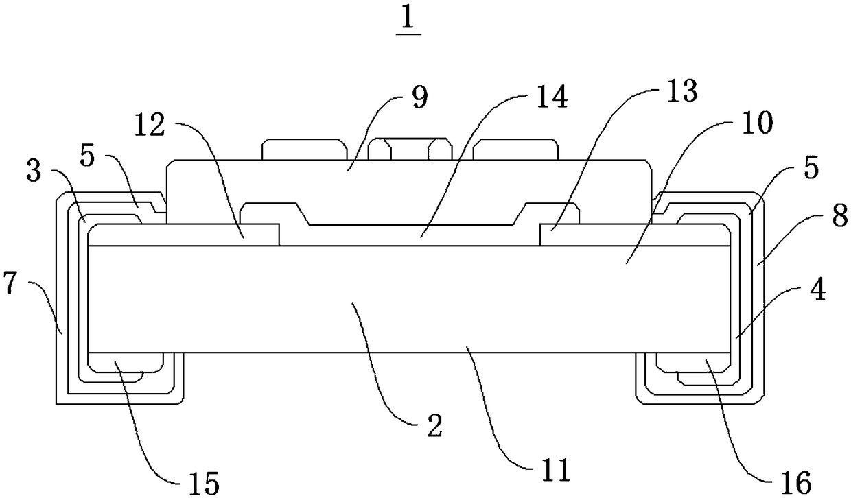
[0040] Please refer to figure 1 , the embodiment of the present invention provides a thin-film low-resistance 1, which uses a thin-film low-resistance L-type resistance adjustment method to adjust resistance.

[0041] Wherein, the thin film low resistance 1 includes a ceramic substrate 2, a first end face electrode 3, a second end face electrode 4, a first metal barrier layer 5, a second metal barrier layer 6, a first solder outer layer 7, a second solder outer layer layer 8 and protective layer 9; ceramic substrate 2 has opposite first side 10 and second side 11, and first side 10, second side 11 all extend along the length direction of ceramic substrate 2; first side 10 is close to ceramic Both ends of the substrate 2 are provided with a first surface electrode 12 and a second surface electrode 13, and a resistor 14 is arranged between the first surface electrode 12 and the second surface electrode 13; The first back electrode 15 and the second back electrode 16 are arrange...


PUM


Abstract

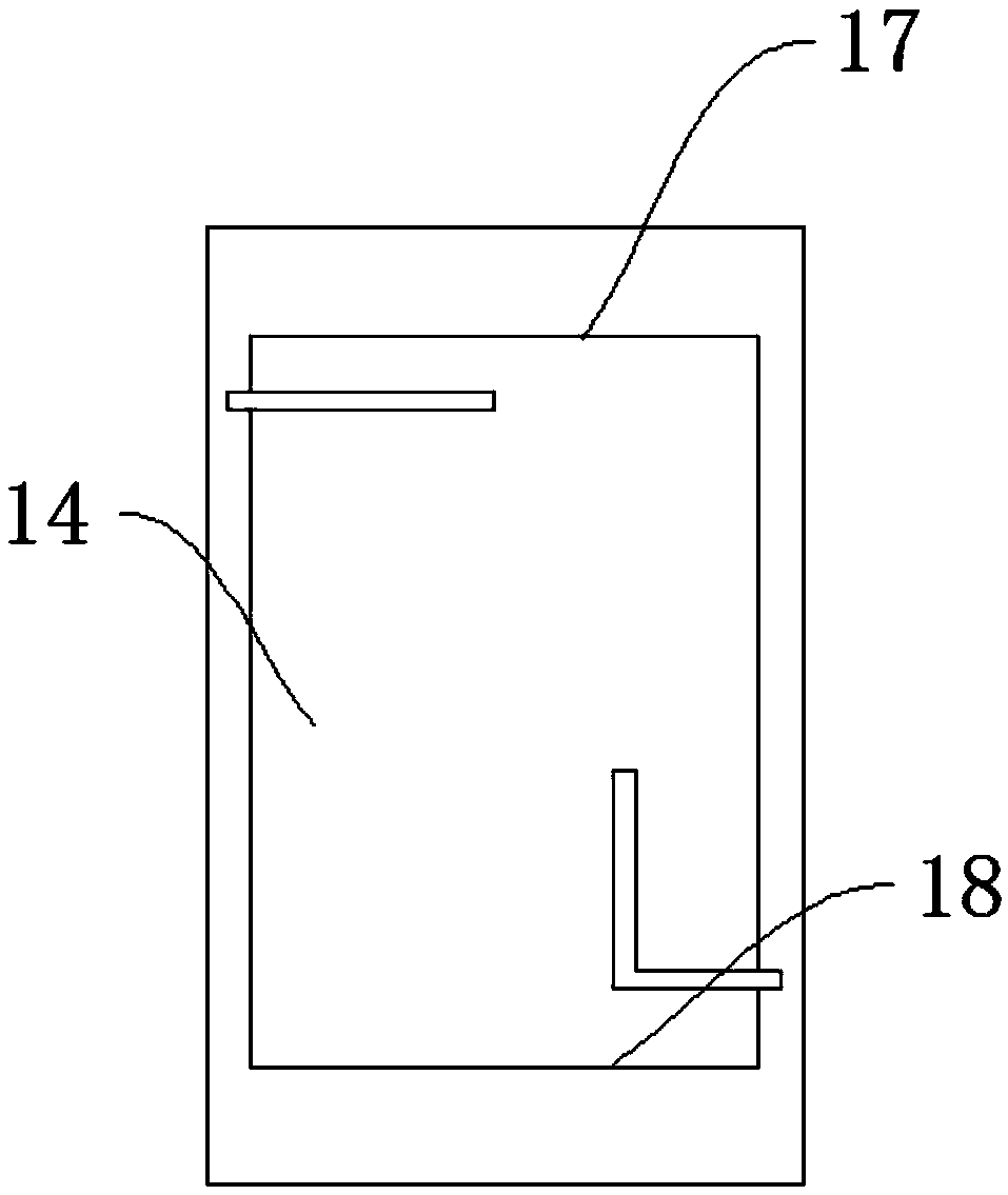
The invention discloses a thin-film low resistor and an L-type resistor adjusting method therefor and relates to the technical field of electronic products. The method comprises the steps of (S1) cutting a linear resistor fine-adjusting port in the position, close to a first end face electrode, of a first side end, wherein the extension direction of the resistor fine-adjusting port is parallel tothe first side end and the vertical interval between the resistor fine-adjusting port and the first end face electrode is 0.2-0.4mm; (S2) cutting an L-type resistor coarse-adjusting port in the position, close to a second end face electrode, of a second side end, wherein the resistor coarse-adjusting port is provided with communicating horizontal adjusting port and vertical adjusting port; the extension direction of the horizontal adjusting port is parallel to the second side end; the extension direction of the vertical adjusting port is vertical to the second side end; the vertical adjustingport extends along the direction far away from the second side end; and the vertical interval between the horizontal adjusting port and the second end face electrode is 0.2-0.4mm; and (S3) debugging the thin-film low resistor at the positions of the resistor fine-adjusting port and the resistor coarse-adjusting port. The thin-film low resistor prepared by adopting the method is high in heat dissipation capability.

Description

technical field [0001] The invention relates to the technical field of electronic products, and in particular to a thin-film low-resistance and a thin-film low-resistance L-type resistance adjustment method. Background technique [0002] With the development of electronic technology, chip-type thin-film fixed resistors are the basis of high-precision integrated circuits due to their low temperature coefficient, high resistance consistency, and small parasitic capacitance. With the further development of integrated circuits in the direction of high precision and high stability, domestic thin film low resistance has been more widely used. [0003] In the past two years, the use of chip-type thin-film high-power resistors (type 3225, type 5025, and type 6332) has gradually increased, and the demand for higher power has been raised. The laser trimming method is the key factor affecting the power of the product. At present, for conventional The laser resistance trimming process ...

Claims


Application Information

Patent Timeline
IPC IPC(8): H01C7/00H01C17/242
CPCH01C7/006H01C17/242
Inventor 芮家群叶萍韩玉成罗彦军郑犇
Owner CHINA ZHENHUA GRP YUNKE ELECTRONICS
Learn More