Dynamic energy release device and equipment and DC power transmission system

A technology of direct current transmission system and direct current transmission line, which is applied in the direction of circuit devices, emergency protection circuit devices, emergency protection circuit devices for limiting overcurrent/overvoltage, etc., and can solve threats to the safe and stable operation of the system and the weak connection of the AC system , thermal power unit overspeed and other issues, to reduce the risk of transient instability, prevent a large amount of power transfer, improve safety and stability

Pending Publication Date: 2018-11-06
STATE GRID CORP OF CHINA +2
View PDF0 Cites 0 Cited by
  • Summary
  • Abstract
  • Description
  • Claims
  • Application Information

AI Technical Summary

Problems solved by technology

The continuous improvement of UHV DC single-circuit transmission capacity makes the characteristics of "strong DC and weak AC" appear, which are mainly reflected in: first, the receiving end power grid is mostly a load center, and multiple DC feed-in locations are concentrated, and the electrical distance between inverter stations is relatively short. Nearby, the failure of the AC system near the converter station may lead to multiple DC commutation failures at th...

Method used


Image

  • Dynamic energy release device and equipment and DC power transmission system
  • Dynamic energy release device and equipment and DC power transmission system
  • Dynamic energy release device and equipment and DC power transmission system

Examples


Embodiment Construction

[0026] The technical solutions of the present invention will be clearly and completely described below in conjunction with the accompanying drawings. Apparently, the described embodiments are some of the embodiments of the present invention, but not all of them. Based on the embodiments of the present invention, all other embodiments obtained by persons of ordinary skill in the art without making creative efforts belong to the protection scope of the present invention. In addition, the terms "first", "second", etc. are used for descriptive purposes only, and should not be construed as indicating or implying relative importance.

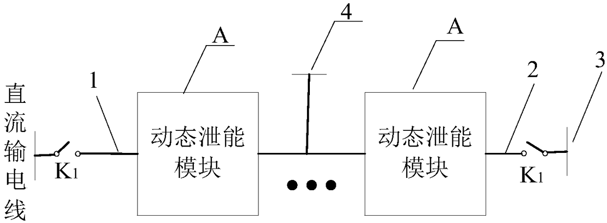
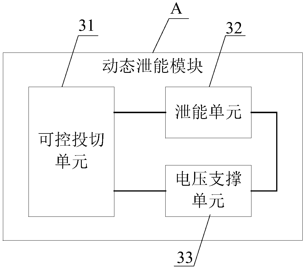
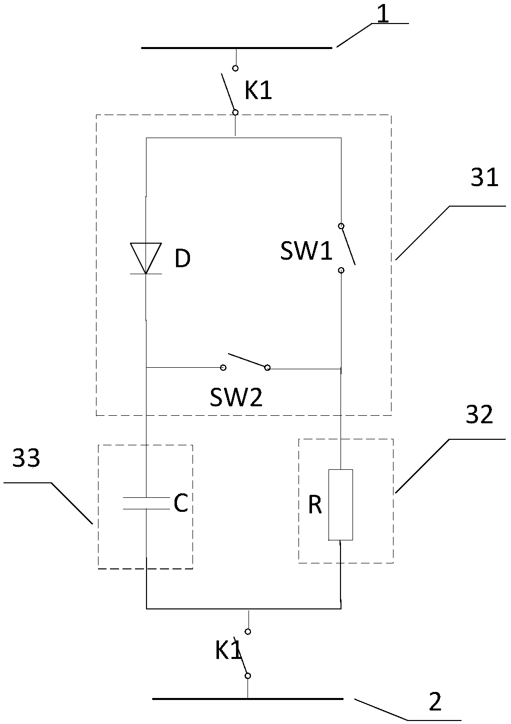
[0027] The embodiment of the present invention provides a dynamic energy discharge device, which can be installed on the DC power transmission system, and when the continuous commutation fails in the DC power transmission system, the DC power at the power transmission end is discharged, which is more effective in preventing power transmission A large ...


PUM


Abstract

The invention provides a dynamic energy release device and equipment and a DC power supply system. The dynamic energy release device comprises at least two dynamic energy release modules which are connected in series between a DC power transmission line and a first ground wire. A first switch is arranged between the input end of the dynamic energy release modules and the DC power transmission lineand/or the first switch is arranged between the grounding end of the dynamic energy release modules and the first ground wire. A second ground wire is connected between the at least two series connected dynamic energy release modules. The first switch is disconnected in case of fault elimination of continuous phase change failure of the DC power transmission system so that the dynamic energy release device can be quickly cut off, the problem of slow system recovery caused by capacitance charging in the recovery process of the DC power supply system can be avoided, and the system is enabled toquickly recover normal operation. The second ground wire is arranged between the series connected dynamic energy release modules so that the system insulation level can be effectively reduced.

Description

technical field [0001] The invention relates to the technical field of direct current transmission, in particular to a dynamic energy discharge device, equipment and a direct current transmission system. Background technique [0002] With the gradual implementation of the "West-to-East Power Transmission" strategy, the UHV DC transmission project has been put into operation intensively, and my country has built the AC-DC hybrid power grid with the largest capacity and the most complex topology in the world. The continuous improvement of UHV DC single-circuit transmission capacity makes the characteristics of "strong DC and weak AC" appear, which are mainly reflected in: first, the receiving end power grid is mostly a load center, and multiple DC feed-in locations are concentrated, and the electrical distance between inverter stations is relatively short. Nearby, the failure of the AC system near the converter station may lead to multiple DC commutation failures at the same t...

Claims


Application Information

Patent Timeline
IPC IPC(8): H02J3/36H02H9/04
CPCH02H9/042H02J3/36Y02E60/60
Inventor 魏晓光李方媛寇龙泽刘栋翟雪冰江晨高路
Owner STATE GRID CORP OF CHINA
Why Eureka
Try Eureka