On-load tap changer and method thereof
An on-load tap and switch technology, applied in electronic switches, electrical components, thyristors, etc., can solve problems such as complex structure, and achieve the effects of small size, high reliability and simple mechanical structure
- Summary
- Abstract
- Description
- Claims
- Application Information
AI Technical Summary
Problems solved by technology
Method used
Image
Examples
Embodiment 1
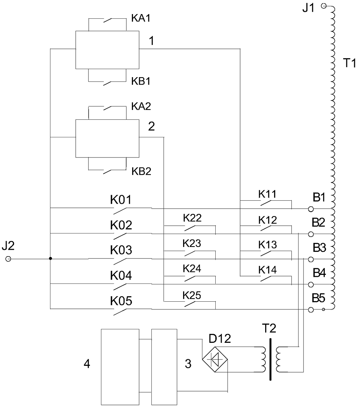
[0070] For the convenience of description, the structure and working principle of the first simple and simple structure of the on-load tap-changer is described by taking the voltage regulating transformer with 5 taps as an example. Of course, in other embodiments, the number of taps can be replaced, decreased or increased, and this data is set for convenience of description, and is not limited thereto.
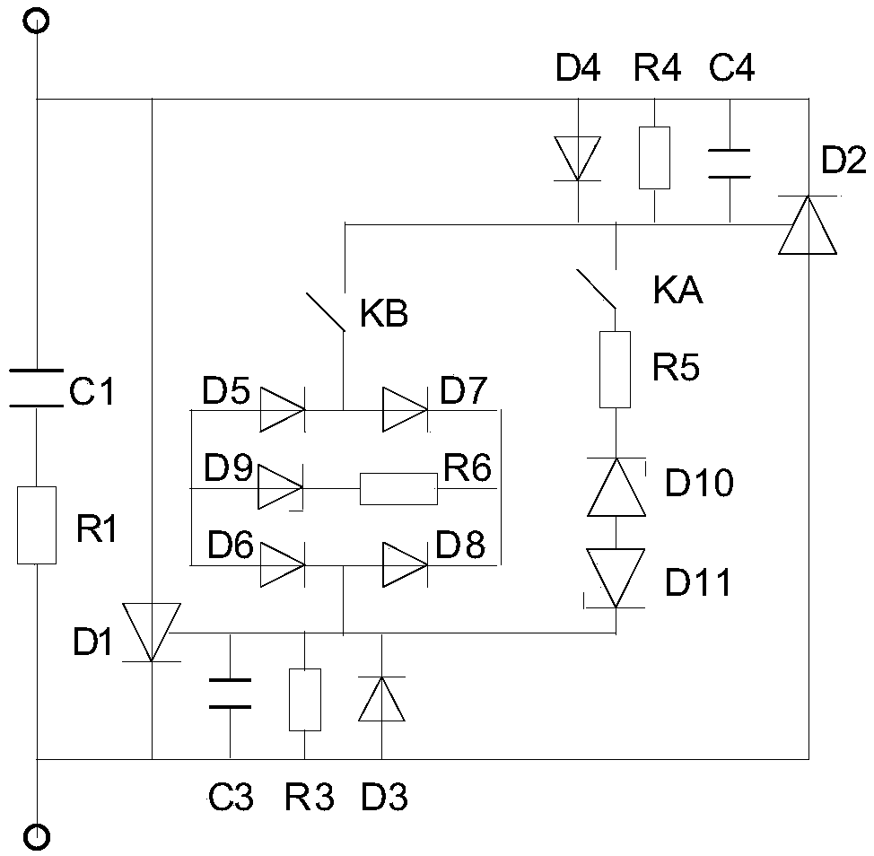
[0071] The structure of the first type of on-load tap-changer with simple structure is as follows: figure 1 shown. The two terminals J1 and J2 of the voltage regulating transformer are connected to the power system, and one end of the voltage regulating coil of the voltage regulating transformer is connected to J1; one end of the five main switches inside the first type of on-load tap changer with simple structure is respectively connected to the voltage regulating transformer The 5 taps B1, B2, B3, B4, B5, B6, the other end of the 5 main switches are connected to the termina...
Embodiment 2
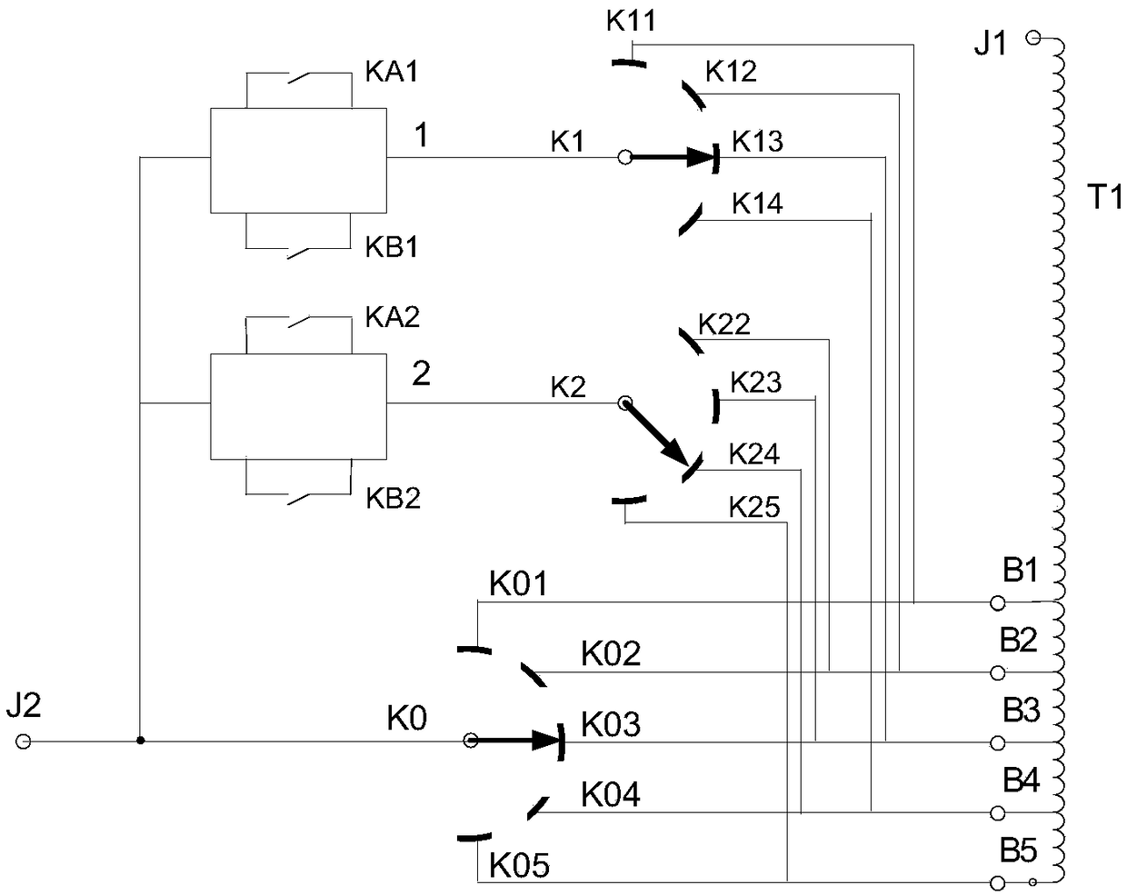
[0096] For the convenience of description, the structure and working principle of the third simple and simple structure of the on-load tap-changer is described by taking the voltage regulating transformer with 5 taps as an example.
[0097]The third type of structure is simple on-load tap-changer structure, such as Figure 4 shown. The two terminals J1 and J2 of the voltage regulating transformer are connected to the power system, and one end of the voltage regulating coil of the voltage regulating transformer is connected to J1; one end of the five main switches inside the on-load tap-changer with a simple structure is connected to the voltage regulating transformer respectively. The 5 taps B1, B2, B3, B4, B5, B6, the other end of the 5 main switches are connected to the terminal J2; when any one of the main switches is closed, the voltage regulating coil of the voltage regulating transformer can flow current; different main switches are closed , the voltage regulating trans...
Embodiment 3
[0107] The sixth type of on-load tap changer with simple structure is used when the tap of the voltage regulating transformer is located in the middle of the voltage regulating coil. For the convenience of description, the structure and working principle of the third simple and simple structure of the on-load tap-changer is described by taking a voltage regulating transformer with 6 taps as an example.
[0108] The sixth structure is a simple structure of the on-load tap-changer, such as Figure 7 shown. The voltage regulating transformer has two terminals J1 and J2 connected to the power system. The beginning of the upper voltage regulating coil of the voltage regulating transformer is connected to terminal J1, and the end of the upper voltage regulating coil has taps B1, B3, B5. The lower part of the voltage regulating transformer There are taps B2, B4, and B6 at the beginning of the coil, and the end of the lower voltage regulating coil is connected to terminal J2; the six...
PUM
 Abstract
Description
Claims
Application Information
 - R&D
- Intellectual Property
- Life Sciences
- Materials
- Tech Scout
- Unparalleled Data Quality
- Higher Quality Content
- 60% Fewer Hallucinations
Browse by: Latest US Patents, China's latest patents, Technical Efficacy Thesaurus, Application Domain, Technology Topic, Popular Technical Reports.
© 2025 PatSnap. All rights reserved.Legal|Privacy policy|Modern Slavery Act Transparency Statement|Sitemap|About US| Contact US: help@patsnap.com


