Urodynamic monitoring system and drainage monitoring control unit thereof

A monitoring control and monitoring system technology, applied in the field of medical devices, can solve the problems of inability to accurately monitor intravesical pressure, inability to continuously and dynamically reflect intra-abdominal pressure, inability to achieve bionic urination, and achieve novel design, reasonable structure, and avoidance of interference. Effect

Pending Publication Date: 2018-11-09
ZHEJIANG LEXIN MEDICAL TECH CO LTD
View PDF0 Cites 3 Cited by
  • Summary
  • Abstract
  • Description
  • Claims
  • Application Information

AI Technical Summary

Problems solved by technology

[0009] The present invention mainly aims to solve the technical defects in the prior art that the pressure in the bladder cannot be accurately monitored, thus the bionic urinary continence cannot be realized, and the intra-abdominal pressure

Method used


Image

  • Urodynamic monitoring system and drainage monitoring control unit thereof
  • Urodynamic monitoring system and drainage monitoring control unit thereof
  • Urodynamic monitoring system and drainage monitoring control unit thereof

Examples


Embodiment 1

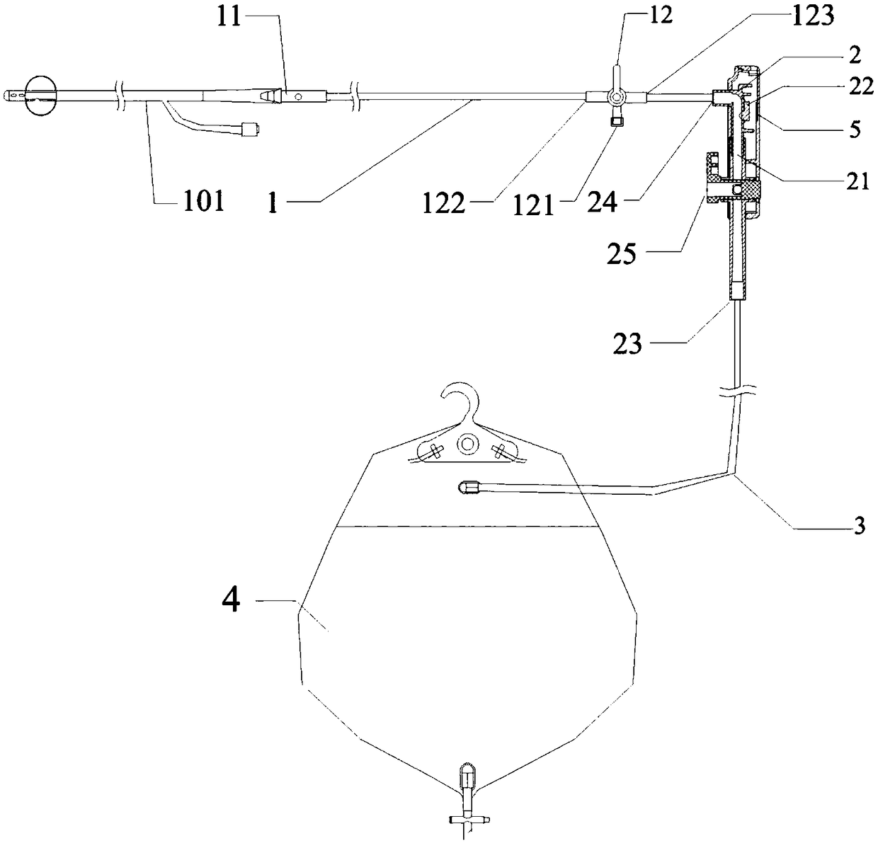
[0029] Embodiment 1: as attached figure 2 As shown, the present invention includes a front drainage pipeline 1, a monitoring controller 2, a rear drainage pipeline 3, a urine storage bag 4, and an electronic tag 5;

[0030] The monitoring controller 2 includes a monitoring and control chamber 21 that is provided with a urine outlet 23 that is communicated with the urine storage bag 4 through the rear drainage pipeline 3 and a urine inlet 24 that is connected with the front drainage pipeline 1, a monitoring component 22, and a control chamber. The valve 25, the monitoring part 22 monitors and monitors the urine pressure in the control chamber 21 and outputs a pressure signal, and the control valve 25 controls the connection or blocking between the urine inlet 24 and the urine outlet 23;

[0031] The front drainage pipeline 1 includes a joint 11 connected to the indwelling urinary catheter 101 and a first three-way valve 12;

[0032] The first three-way valve 12 has an atmosph...

Embodiment 2

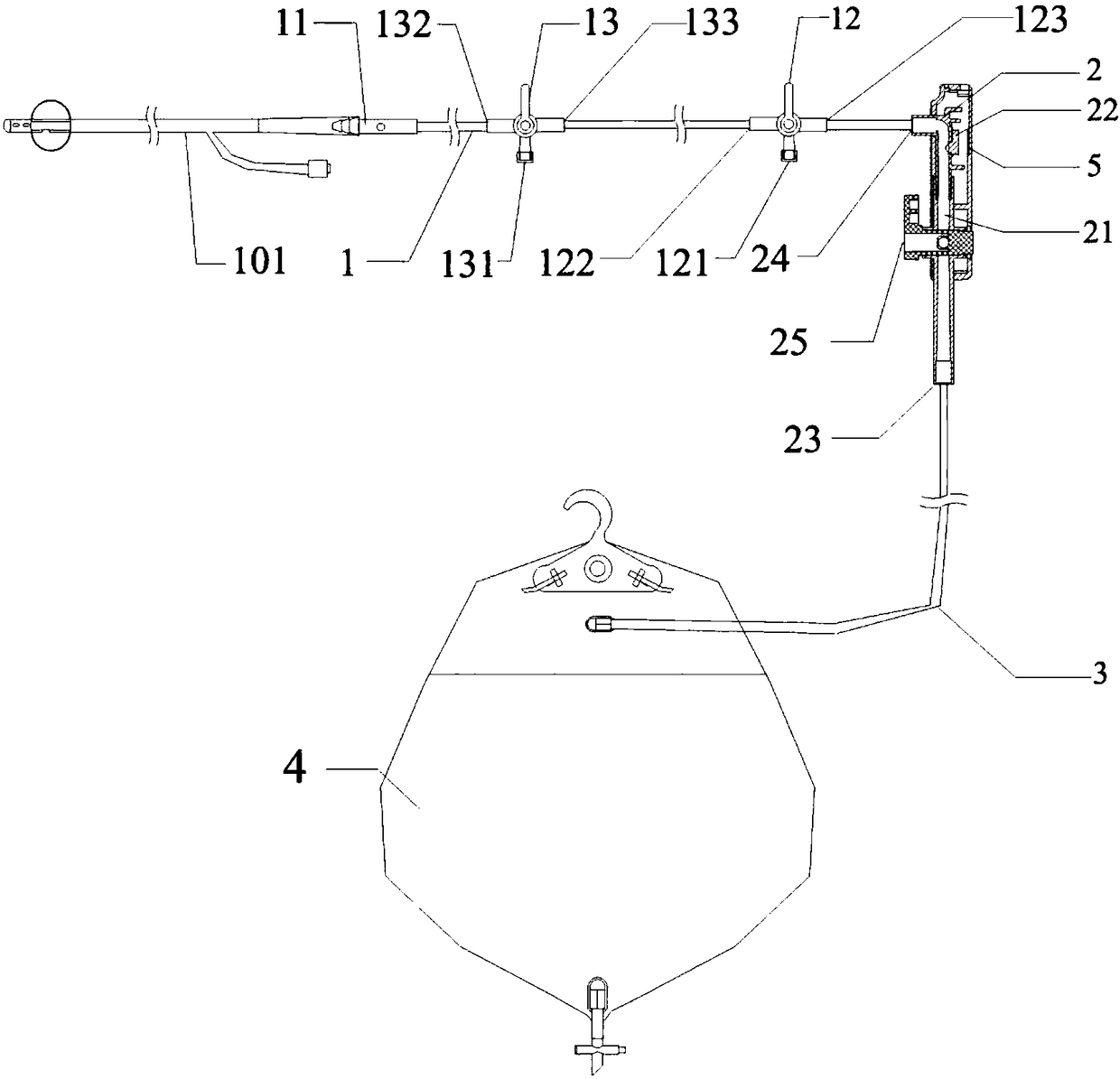
[0034] Embodiment 2: as attached image 3 As shown, the present invention includes a front drainage pipeline 1, a monitoring controller 2, a rear drainage pipeline 3, a urine storage bag 4, and an electronic tag 5;

[0035] The monitoring controller 2 includes a monitoring and control chamber 21 that is provided with a urine outlet 23 that is communicated with the urine storage bag 4 through the rear drainage pipeline 3 and a urine inlet 24 that is connected with the front drainage pipeline 1, a monitoring component 22, and a control chamber. The valve 25, the monitoring part 22 monitors and monitors the urine pressure in the control chamber 21 and outputs a pressure signal, and the control valve 25 controls the connection or blocking between the urine inlet 24 and the urine outlet 23;

[0036] The front drainage pipeline 1 includes a joint 11 connected to the indwelling catheter 101, a first three-way valve 12, and a second three-way valve 13;

[0037] The first three-way va...

Embodiment 3

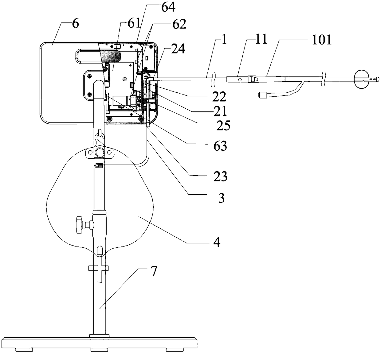
[0040] Embodiment 3: as attached image 3 , attached Figure 4 As shown, the present invention includes a monitoring host 6 composed of a main board 61, a control component 62, a weighing component 63, and a casing 64, an adjustment bracket 7 for fixing and adjusting the position and height of the monitoring host 6, a drainage monitoring control unit 8, and a laser level indicator 9;

[0041] The main board 61, the control part 62, the weighing part 63 and the drainage monitoring control unit 8 are accommodated in the housing 64. The main board 61 receives the pressure signal output by the monitoring part 22, and according to the monitoring and control, the urine in the cavity 21 is blocked and blocked at the atmospheric inlet 121. The atmospheric pressure at the patient's location is obtained by connecting the pressures in the two working states; when the urine pressure in the monitoring control chamber 21 is subtracted from the atmospheric pressure at the patient's location...


PUM


Abstract

The invention relates to a urodynamic monitoring system and a drainage monitoring control unit thereof. The system comprises a mainboard, a control part, a monitoring main unit of a bearing part and the drainage monitoring control unit; the drainage monitoring control unit is formed by connecting a front drainage pipeline, a monitoring controller, a rear drainage pipeline and a urine storage bag in sequence, and the front drainage pipeline is provided with a first three-way valve capable of being communicated with the atmosphere. Accordingly, by arranging the first three-way valve capable of being communicated with the atmosphere on the front drainage pipeline, by switching the working conditions of the first three-way valve, atmospheric pressure of the position where a bladder is locatedis measured, and an accurate bladder internal pressure value is obtained by subtracting the atmospheric pressure of the position where the bladder is located from urine pressure in a monitoring control cavity; the technical problem that in the prior art, due to the fact that the internal pressure of the ladder cannot be accurately monitored so that bionic urinary continence cannot be achieved, andthe pressure in an abdominal cavity cannot be continuously and dynamically reflected are solved.

Description

technical field [0001] The invention relates to a urodynamic monitoring system and a drainage monitoring control unit thereof, belonging to the field of medical devices. Background technique [0002] Intra-abdominal pressure (IAP) is the internal pressure of the abdominal cavity. It is one of the important physiological parameters for clinical diagnosis and treatment of diseases. Intra-abdominal pressure measurement is the gold standard for indirect method of intra-abdominal pressure measurement. [0003] Clinically, catheterization of patients through an indwelling catheter inserted into the urethra is a routine operation widely used at present. A urodynamic monitoring system that prevents degradation of bladder inflation and contraction function. This urodynamic monitoring system consists of a monitoring host and a drainage monitoring control unit (see attached figure 1 shown), the drainage monitoring control unit is provided with a front drainage pipeline 1 connected to...

Claims


Application Information

Patent Timeline
IPC IPC(8): A61B5/20A61B5/03A61M1/00
CPCA61B5/036A61B5/205A61M2205/3379A61M1/73A61M1/743A61B5/6852G01C9/06G01C2009/066G01G17/06
Inventor 吕百成陈俊杰付飞黎国荣
Owner ZHEJIANG LEXIN MEDICAL TECH CO LTD
Why Eureka
Try Eureka