Chemical barrel cleaning equipment
A technology for cleaning equipment and chemical barrels, which is applied in the field of chemical barrel cleaning equipment, can solve the problems of high labor intensity, large water consumption, and low work efficiency, and achieve the effects of reducing labor intensity, improving cleaning speed, and novel structure
- Summary
- Abstract
- Description
- Claims
- Application Information
AI Technical Summary
Problems solved by technology
Method used
Image

Examples
Embodiment 1
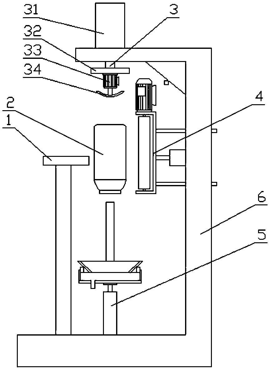
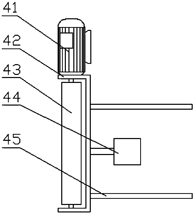
[0027] Such as Figure 1 to Figure 4 Shown; A kind of chemical barrel cleaning equipment, comprises chemical barrel conveying mechanism 1, chemical barrel 2, power rotating mechanism 3, outer wall cleaning mechanism 4, cleaning mechanism 5 and frame 6, described power rotating mechanism 3, outer wall cleaning mechanism 4 and the cleaning mechanism 5 are all arranged on the frame 6, and the chemical barrel 2 is transported between the power rotating mechanism 3 and the cleaning mechanism 5 through the chemical barrel conveying mechanism 1, and the power rotating mechanism 3 is located above the chemical barrel 2. The cleaning mechanism 5 is located below the chemical barrel 2; the outer wall cleaning mechanism 4 is arranged on one side of the chemical barrel 2; the mouth of the chemical barrel 2 cooperates with the cleaning end of the cleaning mechanism 5; the outer wall cleaning mechanism 4 includes an outer wall cleaning A motor 41, a water retaining box 42 and a traverse cyl...
Embodiment 2
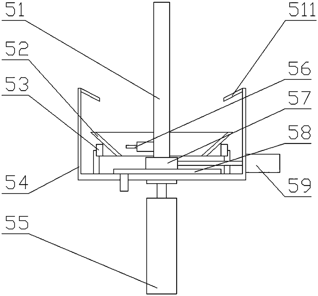
[0033] On the basis of Embodiment 1, it also includes a moving block 57, a slide rail 58 and a cleaning roller moving cylinder 59. The slide rail 58 is arranged in the sewage tank 54, and the moving block 57 is arranged on the slide rail 58. The cleaning roller 51 is connected on the moving block 57, and the cleaning roller moving cylinder 59 is arranged on one side of the sewage tank 54, and the power rod of the cleaning roller moving cylinder 59 penetrates the side wall of the sewage tank 54 and is connected on the moving block 57; the control The device is electrically connected to the moving cylinder 59 of the cleaning roller; one end of the cleaning roller 51 is provided with a travel switch 56, and the travel switch 56 is located at one end close to the V-shaped rotating disk 52, and the travel switch 56 is connected to the opening of the chemical barrel 2. Cooperate; the controller is electrically connected to the travel switch 56; it also includes a shaft sleeve and a g...
Embodiment 3
[0036] On the basis of Embodiment 2, it also includes a scraper 47 and a spring 46. The scraper 47 is hinged on both sides of the water retaining box 42. The middle part of the scraper 47 is connected to the water retaining box 42 through a spring 46. The scraper The plate 47 cooperates with the outer wall of the chemical barrel 2; the water retaining box 42 is provided with at least one high-pressure nozzle, which communicates with the high-pressure liquid pipe; includes bolts, and the cleaning roller 51 is provided with at least one cleaning brush installation groove, so The bolts are arranged on the cleaning roller 51, and the cleaning brush is fixed in the installation groove by bolts; the water-retaining curtain is arranged on the fixing frame 32; a pressure sensor is arranged between the cleaning lifting cylinder 55 and the sewage tank 54; The controller is electrically connected to the pressure sensor.
[0037] Cleaning liquid is sprayed on the external cleaning roller ...
PUM
 Abstract
Description
Claims
Application Information
 - R&D
- Intellectual Property
- Life Sciences
- Materials
- Tech Scout
- Unparalleled Data Quality
- Higher Quality Content
- 60% Fewer Hallucinations
Browse by: Latest US Patents, China's latest patents, Technical Efficacy Thesaurus, Application Domain, Technology Topic, Popular Technical Reports.
© 2025 PatSnap. All rights reserved.Legal|Privacy policy|Modern Slavery Act Transparency Statement|Sitemap|About US| Contact US: help@patsnap.com