Mixing valve element automatic assembly line

A technology of mixing valve and assembly line, which is applied in the field of automatic assembly line of mixing valve core, can solve the problems of cumbersome installation work, consumption, and many manpower, and achieve the effects of reducing labor costs, increasing production efficiency, and increasing efficiency

Pending Publication Date: 2018-11-09
福建瑞德成自动化科技有限公司
View PDF1 Cites 6 Cited by
  • Summary
  • Abstract
  • Description
  • Claims
  • Application Information

AI Technical Summary

Problems solved by technology

[0004] like figure 1 As shown, similar to the above in the prior art, it generally includes a valve body, a gasket, a lever, a bracket, a rotating shaft, a moving ceramic piece, a base, an inner O-ring, a static ceramic piece, a large O-ring and an outer O-ring. Simple, but the installation work is relatively cumbersome. In the prior art, it is generally assembled manually, which requires a lot of manpower

Method used


Image

  • Mixing valve element automatic assembly line
  • Mixing valve element automatic assembly line
  • Mixing valve element automatic assembly line

Examples


Embodiment Construction

[0046] The present invention will be described in further detail below in conjunction with the accompanying drawings.

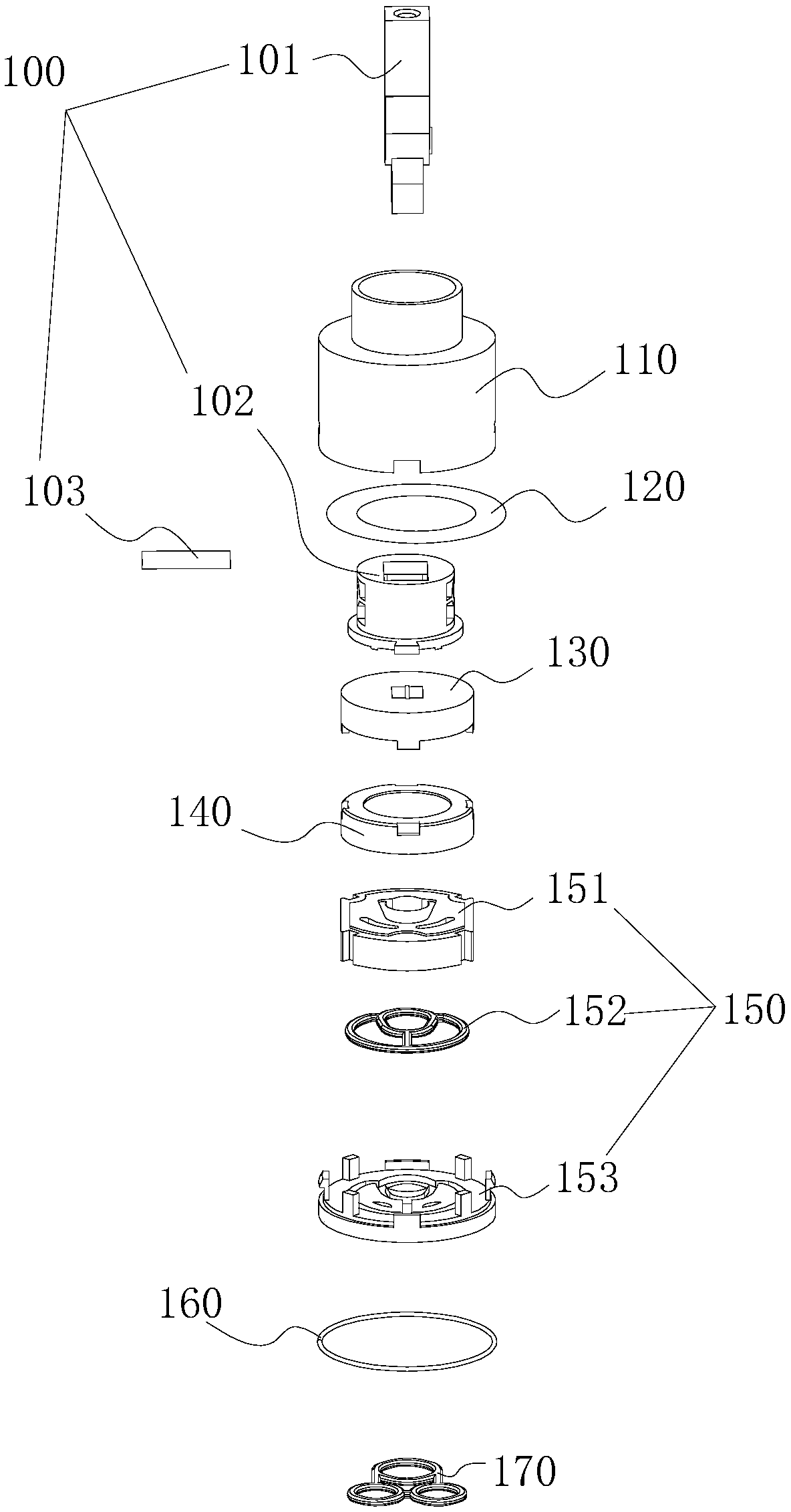
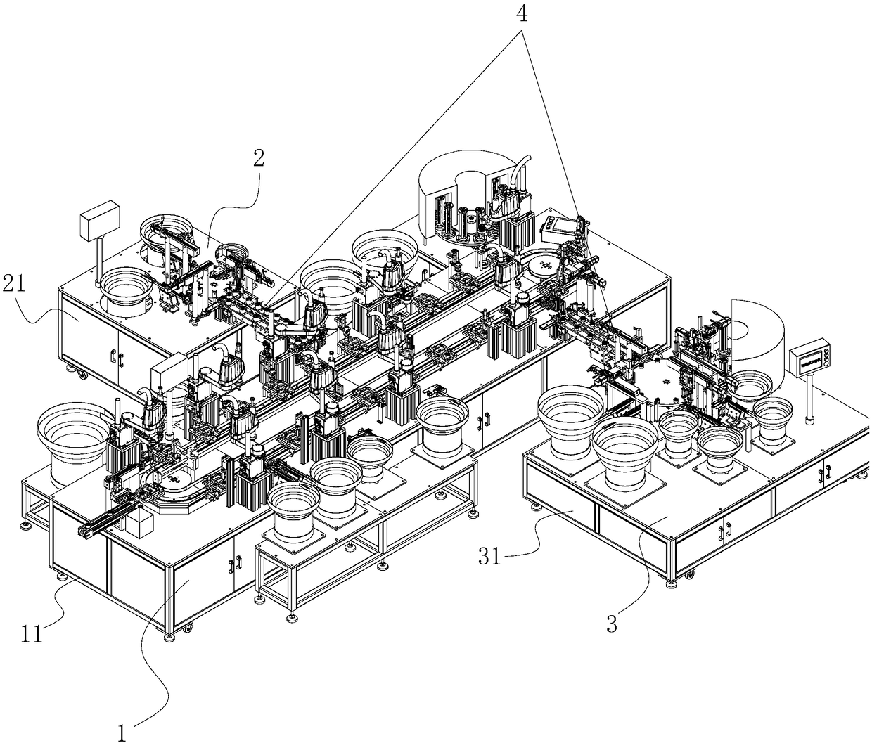
[0047] A hybrid spool automatic assembly line, such as figure 2 As shown, it includes the first auxiliary assembly line 2 for assembling the lever 101, the bracket 102 and the rotating shaft 103 together to form the valve stem assembly 100 in sequence, and the first auxiliary assembly line 2 for assembling the base 153, the inner O-ring 152 and the static ceramic plate 151 Assembled together in turn to form the second auxiliary assembly line 3 of the end cap assembly 150 and for the valve body 110, the gasket 120, the valve stem assembly 100, the dial 130, the moving ceramic piece 140, the end cap assembly 150, the large O The ring 160 and the outer O-ring 170 are assembled together in turn to form a complete assembly line 1 of the mixing valve core, wherein, between the first auxiliary assembly line 2 and the final assembly line 1 and the second auxiliary a...


PUM


Abstract

The invention discloses a mixing valve element automatic assembly line, and relates to an automatic production system of a valve element. The assembly line comprises a first auxiliary assembling lineused for sequentially assembling a stirring rod, a support and a rotating shaft to combine a valve rod assembly, a second auxiliary assembling line used for sequentially assembling a base, an inner Oring and a fixed ceramic piece to combine an end cover assembly, a final assembly line used for sequentially assembling a valve body, a gasket, a valve rod assembly, a stirring disc, a movable ceramicpiece, an end cover assembly, a large O ring and an outer O ring to combine a complete mixing valve element and two assembly conveying lines arranged between the first auxiliary assembling line and the final assembly line and between the second auxiliary assembling line and the final assembly line and used for conveying a valve rod assembly and an end cover assembly to the final assembly line. The beneficial effects of being high in automation degree and free of artificial participation are achieved.

Description

technical field [0001] The invention relates to an automatic production system of a valve core, more specifically it relates to an automatic assembly line for a mixed valve core. Background technique [0002] The mixing spool refers to the spool that can individually control the cold water or hot water outlet and the mixed hot and cold water outlet. Compared with the conventional upper water outlet spool, its function is more powerful, so it is more popular among customers. [0003] At present, the Chinese patent with the authorized notification number CN206309990U discloses a water outlet mixing valve core, which includes a closed chamber formed by a base and a cover, and a hot water hole connecting the chamber and the hot water pipe is arranged on the base , the cold water hole connecting the chamber and the cold water pipe, and the return hole connecting the chamber and the shower head. The chamber is provided with a ceramic static piece and a ceramic moving piece whose e...

Claims


Application Information

Patent Timeline
Patent Type & Authority Applications(China)
IPC IPC(8): B23P21/00
CPCB23P21/004
Inventor 温维坤王光荣温遗福
Owner 福建瑞德成自动化科技有限公司
Why Eureka
Try Eureka