Slag weight estimation method and slag weight estimation device
A technology for weight and slag, applied in the field of slag discharge weight estimation and slag discharge weight estimation device, can solve the problem of inability to apply desiliconization to slag, and achieve the effects of improving iron yield, reducing slag production, and suppressing heat loss
- Summary
- Abstract
- Description
- Claims
- Application Information
AI Technical Summary
Problems solved by technology
Method used
Image
Examples
Embodiment 1
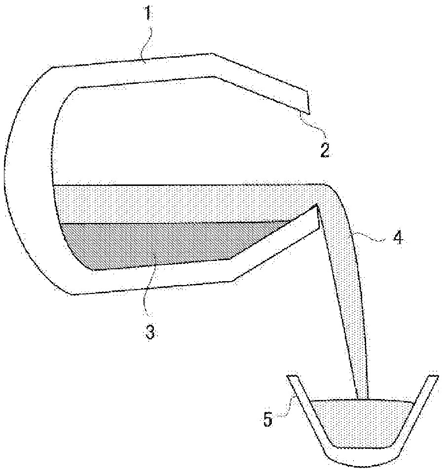
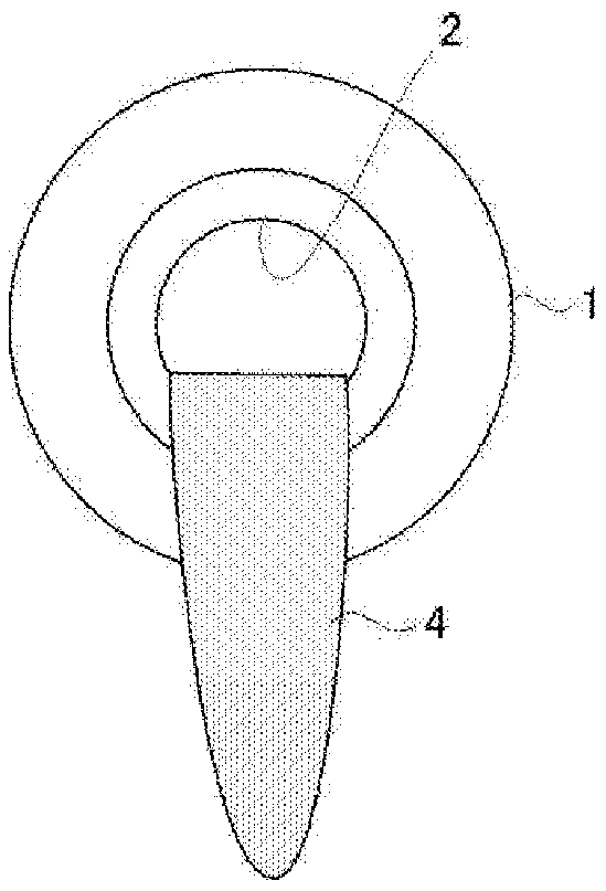
[0055] The slagging operation was carried out in a 350 ton scale top-bottom blown converter, and the slagging weight of the slag was estimated. The inner diameter of the furnace mouth of the converter is about 4.6m, the inner diameter of the cylindrical main body of the converter is about 6.6m, and the distance from the upper end of the cylindrical main body to the furnace mouth is about 2.7m.
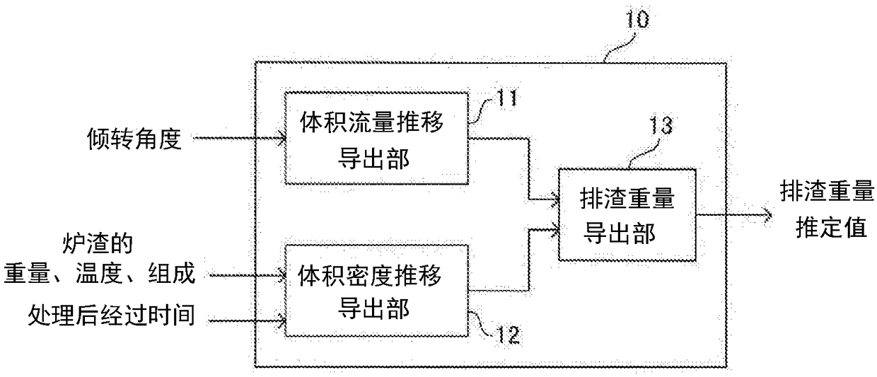
[0056] First, by using computational fluid dynamics, the volume flow rate Q of the slag discharged from the converter is calculated using the shape of the converter and the assumed time-dependent change pattern of the tilt angle of the converter as calculation input conditions. S , and make the tilting speed of the converter and the volume flow Q of the slag discharged from the converter S The relationship produces a corresponding regression. Then, by substituting the tilting speed obtained from the time-dependent change in the tilting angle of the converter during the slagging operat...
Embodiment 2
[0060] The slagging operation was carried out several times, and in each operation, the estimated value of the slagging weight of the slag was derived using the method of the embodiment of the disclosed technology. Furthermore, in each operation, the estimated value of the discharged slag weight of slag was derived using the method (comparative example 1) by an operator and the method described in Unexamined-Japanese-Patent No. 2007-308773 (comparative example 2). In addition, in each operation, the slag discharge weight of the slag was obtained by weighing the real value with a scale. In addition, in the estimation of the slag discharge weight of the slag performed using the method described in Japanese Patent Laid-Open No. 2007-308773 (Comparative Example 2), the weight of the slag remaining in the converter is estimated from the final inclination angle of the converter. Volume, the volume density of the slag remaining in the converter is kept constant, and the slag discharg...
Embodiment 3
[0064] Using the same converter as in Example 1, a test for evaluating the effect of reducing the amount of auxiliary raw materials used was implemented. After putting scraps and molten pig iron into the converter, according to the amount of molten pig iron and silicon concentration, auxiliary raw materials such as quicklime are charged into the converter, and the molten iron is dephosphorized so that the alkalinity of the slag falls within a predetermined range. Thereafter, the converter is tilted to discharge a part of the slag in the upper layer from the furnace mouth, and then the converter is vertically erected again and auxiliary raw materials are added to continue the decarburization treatment. At this time, the slag discharge weight of the slag is estimated by the method of the embodiment of the disclosed technology and the conventional method of visually observing by an operator, and the amount of the auxiliary raw material to be added in the decarburization treatment ...
PUM
 Abstract
Description
Claims
Application Information
 - R&D
- Intellectual Property
- Life Sciences
- Materials
- Tech Scout
- Unparalleled Data Quality
- Higher Quality Content
- 60% Fewer Hallucinations
Browse by: Latest US Patents, China's latest patents, Technical Efficacy Thesaurus, Application Domain, Technology Topic, Popular Technical Reports.
© 2025 PatSnap. All rights reserved.Legal|Privacy policy|Modern Slavery Act Transparency Statement|Sitemap|About US| Contact US: help@patsnap.com


