Automatic grinding machine for industrial machinery and grinding method

A technology for industrial machinery and grinding machines, applied in grinding machines, manufacturing tools, grinding racks, etc., can solve the problems affecting the production and sales of workpieces, scratches on the surface of workpieces, and low efficiency of grinding discs, so as to achieve good product quality and avoid workpieces. Deformation, the effect of improving work efficiency

Inactive Publication Date: 2018-11-13
CHENGDU PUJIANG KEXIAN TECH
View PDF0 Cites 50 Cited by
  • Summary
  • Abstract
  • Description
  • Claims
  • Application Information

AI Technical Summary

Problems solved by technology

[0002] At present, in industrial machinery, the grinding machine is an indispensable industrial machinery, which is used for finishing and surface polishing of the workpiece. Although the existing industrial machinery grinding machine has solved the cumbersome manual grinding in the past, it still exists. The following problems: 1: The existing industrial machinery grinding machine has poor flexibility. After fixing the workpiece to be processed by a specific fixture, it can only be polished on a part of the surface of the workpiece. If other positions need to be polished, it needs to be re-ground It is cumbersome to change the angle of the workpiece for clamping, and the work efficiency is low; 2: The existing industrial machinery uses a grinding disc when grinding the curved surface of the workpiece, which is inefficient and time-consuming; 3: The existing industrial machinery is grinding the workpiece The burrs and waste chips generated during grinding are easy to adhere to the surface of the workpiece, which causes scratches on the surface of the workpiece during the grinding process, affecting the production and sales of the workpiece

Method used


Image

  • Automatic grinding machine for industrial machinery and grinding method
  • Automatic grinding machine for industrial machinery and grinding method
  • Automatic grinding machine for industrial machinery and grinding method

Examples


Embodiment Construction

[0022] The following will clearly and completely describe the technical solutions in the embodiments of the present invention with reference to the accompanying drawings in the embodiments of the present invention. Obviously, the described embodiments are only some, not all, embodiments of the present invention. Based on the embodiments of the present invention, all other embodiments obtained by persons of ordinary skill in the art without making creative efforts belong to the protection scope of the present invention.

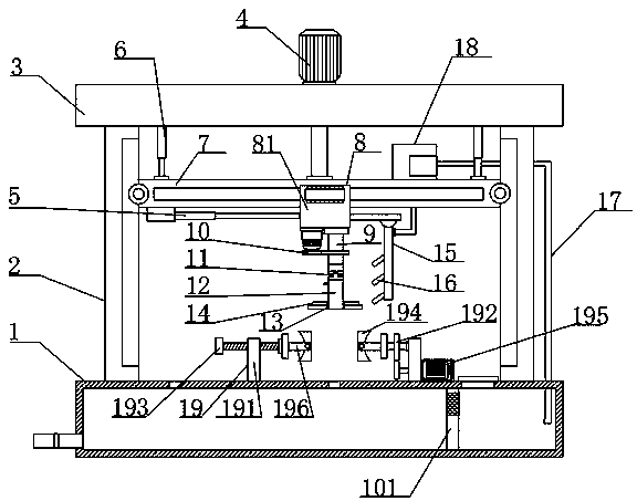
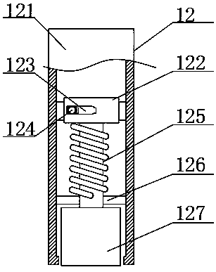
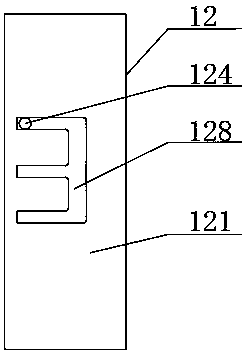
[0023] see Figure 1-3, the present invention provides a technical solution: an automatic grinding machine for industrial machinery, including a base box 1, and the top of the base box 1 is uniformly provided with water outlet holes for collecting and processing water used for grinding, inside the base box 1 A filter plate 101 is arranged vertically on the right side of the cavity, which cooperates with the water pump to separate water and dirt. Columns 2 are ...


PUM


Abstract

The invention discloses an automatic grinding machine for industrial machinery and a grinding method. The automatic grinding machine comprises a base box body, wherein left and right sides of the topof the base box body are symmetrically equipped with stand columns; a top plate is arranged on the tops of the two groups of the stand columns; the outer wall of a bearing rod is movably equipped witha slide assembly; the bottom of the slide assembly is sequentially equipped with a grinding motor and a rotary rod from left to right; the bottom of the rotary rod is equipped with a universal shaftcoupler; the top of the base box body is equipped with a fixed clamp; and the right side of the top of the base bottom box is spliced with a water conveying hose I. The grinding machine for industrialmachinery is high in flexibility and is good in stability; a hydraulic cylinder drives the bearing rod to lift through a pushing rod, so that a grinding disc in grinding can lift; and an electric telescopic pole extends and shortens to drive the slide assembly to move left and right, so that the grinding disc in grinding can move left and right, and therefore, the automatic grinding machine has relatively high flexibility, and improves grinding working efficiency.

Description

technical field [0001] The invention relates to the technical field of industrial machinery, in particular to an automatic grinding machine and a grinding method for industrial machinery. Background technique [0002] At present, in industrial machinery, the grinding machine is an indispensable industrial machinery, which is used for finishing and surface polishing of the workpiece. Although the existing industrial machinery grinding machine has solved the cumbersome manual grinding in the past, it still exists. The following problems: 1: The existing industrial machinery grinding machine has poor flexibility. After fixing the workpiece to be processed by a specific fixture, it can only be polished on a part of the surface of the workpiece. If other positions need to be polished, it needs to be re-ground It is cumbersome to change the angle of the workpiece for clamping, and the work efficiency is low; 2: The existing industrial machinery uses a grinding disc when grinding t...

Claims


Application Information

Patent Timeline
Patent Type & Authority Applications(China)
IPC IPC(8): B24B27/00B24B25/00B24B41/06B24B55/03B24B47/22B24B41/02B24B41/00
CPCB24B27/0076B24B25/00B24B41/005B24B41/02B24B41/06B24B47/22B24B55/03
Inventor 陈清尧
Owner CHENGDU PUJIANG KEXIAN TECH
Why Eureka
Try Eureka