Intelligent punching robot
A punching machine, robot technology, applied in the direction of metal processing, etc., can solve the problem of low efficiency of mechanical punching, and achieve the effect of achieving the level of automation
- Summary
- Abstract
- Description
- Claims
- Application Information
AI Technical Summary
Problems solved by technology
Method used
Image
Examples
Embodiment 1
[0066] Embodiment one: if figure 1 As shown, a copper foil split machine with punching function, the forward direction of installing copper foil includes: unwinding roller 1, punching platform 2 and punching robot 4, driving roller 3, winding roller 8;
[0067] Perforated platform 2 comprises: support column, perforated platform plate 2-1, only strip hole 2-2 is set on perforated platform plate 2-1, waste collection box below perforated platform plate 2, waste material collection box Used to collect punched waste.
[0068] The strip hole 2-2 corresponds to the punching head of the punching robot 4;
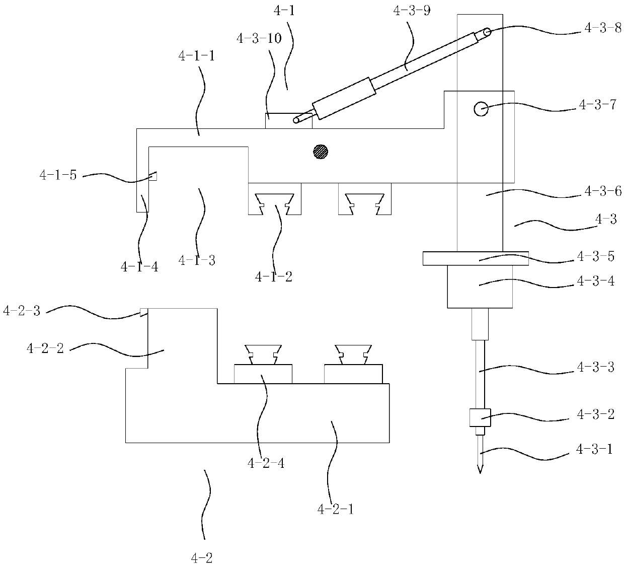
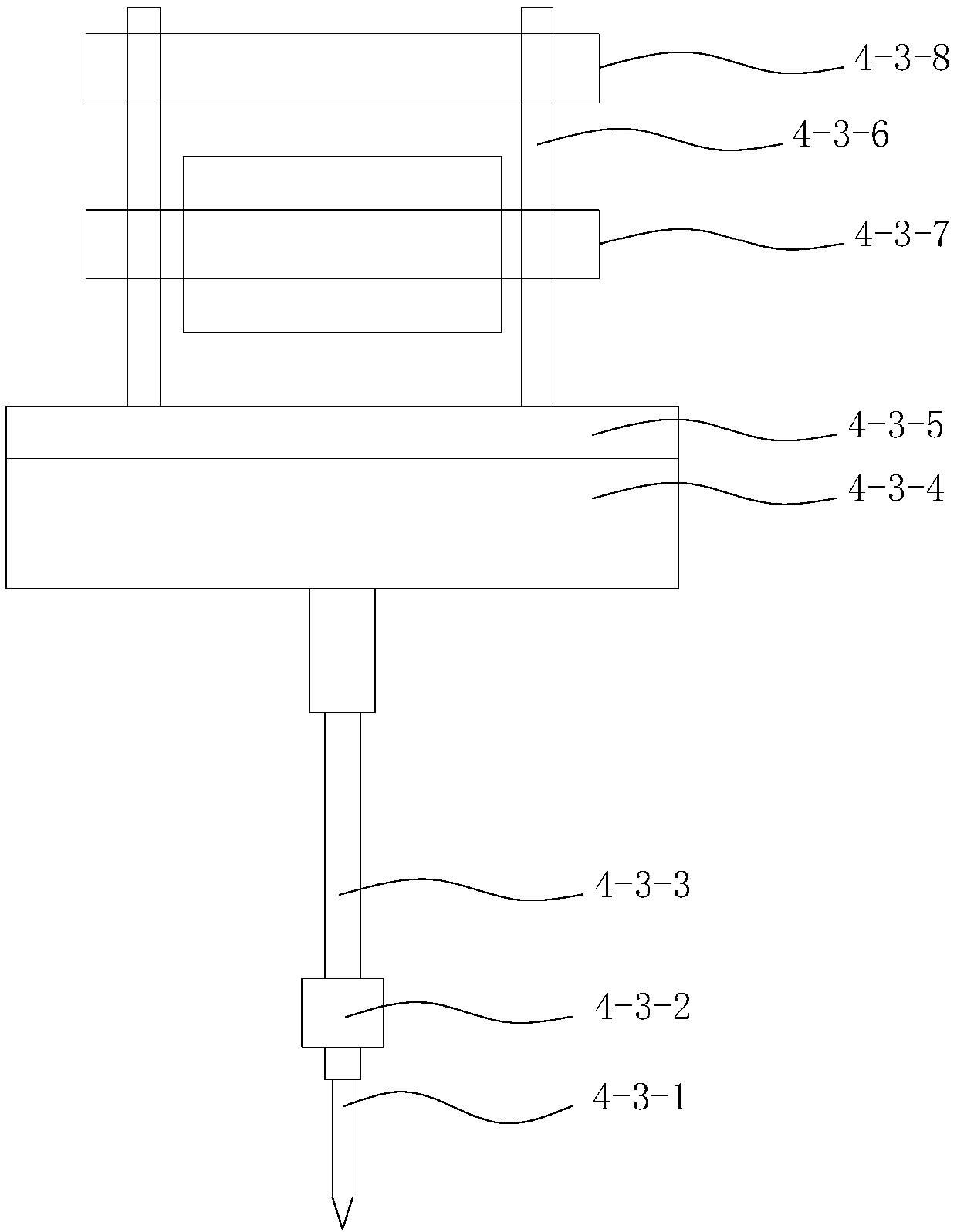
[0069] The punching robot 4 includes: a first punching machine, the first punching machine includes columns respectively located on both sides of the drilling platform, and a first crossbeam 4-2 and a horizontal mover 4 are arranged above the columns of the first punching machine -1. Telescopic puncher 4-3;
[0070] The first crossbeam 4-2 includes: a bearing part 4-2-1, a lock...
Embodiment 2
[0085] The disadvantage of the second embodiment and the first embodiment is that the cross section of the perforated copper foil is easy to oxidize. How to solve this problem is the problem to be solved in the second embodiment.
[0086] The main idea of the second embodiment is to integrate the punching robot and the post-processing mechanism, and its main innovation is that the punching robot is arranged in front of the post-processing machine.
[0087] The post-processing split machine with a punching robot is as follows: the copper foil placed on the unwinding roller is a rough foil, between the punching platform 2, the punching robot 4 and the winding roller 8 of embodiment 1, along the The forward direction of the copper foil is further provided with: an anti-oxidation treatment tank 5 , a cleaning tank 6 , and a drying device 7 .
[0088] After the wool foil is perforated and then treated in the anti-oxidation treatment tank 5 , an anti-oxidation layer can be formed...
Embodiment 3
[0105] Embodiment 3, the requirements for punching holes in copper foil are various. When the hole diameters of copper foil need to be punched are quite different, especially when the two are in close contact, how to punch holes and ensure the quality of punching holes is the first example of Embodiment 2. problem to be solved.
[0106] In the mode of embodiment three, 2 punching machines are arranged to cooperate with the punching platform 2 . The puncher near the unwinding roller is equipped with a punching head with a larger diameter, and the punching machine far away from the unwinding roller is installed with a smaller diameter punching head.
[0107] When carrying out the three punching operations, the effect is: first punch the big hole, then punch the small hole, which is compared to: first punch the small hole, and then punch the big hole, to prevent the two holes when the big hole and the small hole are close to each other. Those who get through, the effect is bette...
PUM
 Abstract
Description
Claims
Application Information
 - R&D
- Intellectual Property
- Life Sciences
- Materials
- Tech Scout
- Unparalleled Data Quality
- Higher Quality Content
- 60% Fewer Hallucinations
Browse by: Latest US Patents, China's latest patents, Technical Efficacy Thesaurus, Application Domain, Technology Topic, Popular Technical Reports.
© 2025 PatSnap. All rights reserved.Legal|Privacy policy|Modern Slavery Act Transparency Statement|Sitemap|About US| Contact US: help@patsnap.com


