Eureka AIR delivers breakthrough ideas for toughest innovation challenges, trusted by R&D personnel around the world.

3D printer forming platform adjusting device and lower projection light curing 3D printer

A 3D printer and adjustment device technology, applied in processing platforms/substrates, 3D object support structures, additive manufacturing, etc., can solve problems such as irreducible errors, printing failures, processing errors, etc., to ensure high consistency and reduce height Error size, effect of improving surface smoothness

Active Publication Date: 2018-11-13
苏州大业三维打印技术有限公司
View PDF4 Cites 4 Cited by
  • Summary
  • Abstract
  • Description
  • Claims
  • Application Information

AI Technical Summary

Problems solved by technology

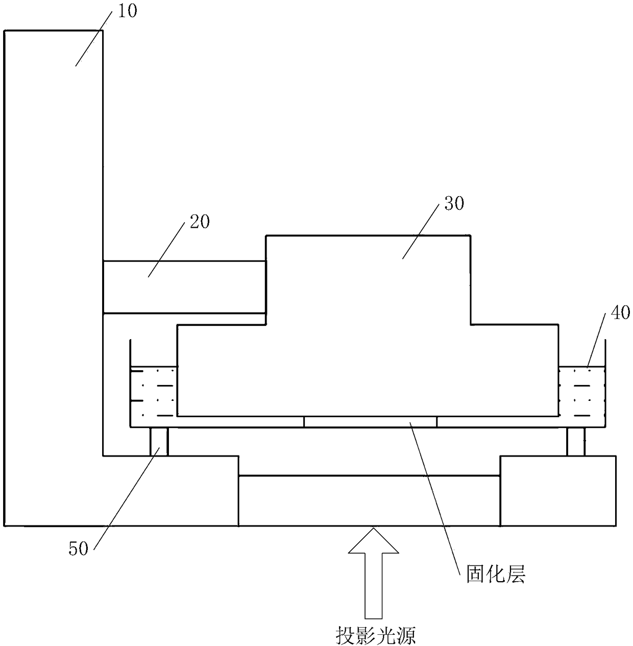
[0009] However, compared to the projection light source, the forming platform 30 is a relatively moving part, while the liquid material box 40 is a relatively stationary part. When errors occur in structural assembly, the errors generated by the forming platform 30 cannot be eliminated due to the rigid connection between the forming platform 30 and the equipment. The adjustment of the material box 40 by the elastic components can ensure that the platform where the bottom surface of the liquid material box 40 is located basically coincides with the projection surface of the projection light source; Pressing down, the liquid material box 40 is deformed with the elastic component to ensure that the bottom surface of the bottom forming platform 30 fits together, so that the bottom surface of the liquid material box 40 and the bottom surface of the forming platform 30 are on the same plane, so that the bottom surface of the liquid material box 40 and the light source cannot be maintained. Vertical, resulting in a large error between the model outline printed on each layer and the theoretical value
In addition, due to the bonding of the forming platform 30 and the liquid material box 40, the compression of the elastic components at both ends is inconsistent, and the difference is finally offset by the first few layers of the model component, resulting in inconsistent heights of the components at both ends of the difference in the compression of the elastic component. The upper and lower surfaces of the construction are not parallel, resulting in large component size errors
[0010] Moreover, since the liquid material box 40 is connected with the equipment through elastic components, every time a layer is printed, the forming platform 30 is pressed down, and the pressure is transmitted to the liquid material box 40 through the liquid resin below the printing object, which may cause the liquid material box Jumping in the horizontal direction, resulting in poor straightness of the printed part in the vertical direction, resulting in greater roughness inside the printed part
[0011] Actually, during the working process of the 3D printer, due to the processing error of the parts of the forming platform 30 and the liquid material box 40 itself, the assembly error caused by human factors in the assembly process, and the cumulative error of the system, the bottom surface of the forming platform 30 and the bottom surface of the liquid material box 40 are in the In the initial state, it is difficult to achieve complete parallelism. When the first layer is printed, the bottom surface of the forming platform 30 and the bottom surface of the liquid material box 40 cannot be completely bonded, and a part of the bottom of the liquid material box 40 is in contact with the bottom surface of the forming platform 30, and the other part is in contact with the forming platform. There is a large gap between 30, which causes the thickness of the resin filled in the large gap to be thicker than that of a single layer of resin curing, the curing cannot be completed, and the formed structural parts cannot be attached to the forming platform, resulting in printing failure

Method used


Image

  • 3D printer forming platform adjusting device and lower projection light curing 3D printer
  • 3D printer forming platform adjusting device and lower projection light curing 3D printer
  • 3D printer forming platform adjusting device and lower projection light curing 3D printer

Examples


Embodiment Construction

[0053] The specific implementation manners of the present invention will be described in more detail below in conjunction with the accompanying drawings and examples, so as to better understand the solution of the present invention and its advantages in various aspects. However, the specific embodiments and examples described below are for the purpose of illustration only, rather than limiting the present invention.

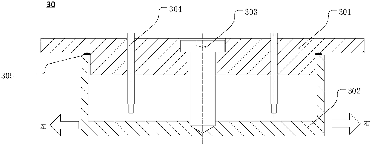
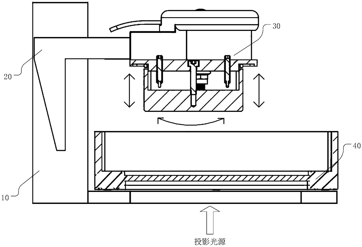
[0054] Such as figure 2 Shown is a schematic structural view of an embodiment of the forming platform adjusting device of the present invention. The forming platform adjustment device is specifically applied to a down-projection light-curing 3D printer, and the forming platform adjustment device includes: a forming seat tray 301 , a forming seat 302 , a tension member 303 and a tightening member 304 . The upper surface of the forming seat tray 301 is crimped on the cantilever 20 of the forming platform, and is provided with at least three first threaded through...


PUM


Abstract

The invention relates to a 3D printer forming platform adjusting device and a lower projection light curing 3D printer. The forming platform adjusting device comprises a forming seat tray, a forming seat, a tension part and fastening parts, wherein the forming seat tray is provided with at least three first threaded through holes, the central lines of the first threaded through holes are not in the same plane, and the upper surface of the forming seat tray is connected to a forming platform cantilever in a pressed mode; the upper surface of the forming seat is opposite to the lower surface ofthe forming seat tray, and the lower surface of the forming seat is used for allowing a to-be-printed target body to be attached; the tension part is of a rod-shaped structure, and one end of the tension part penetrates through the forming seat tray to be fixedly connected with the forming seat and to enable swinging is achieved around the contact part between the tension part and the forming seattray; and the number of the fastening parts is the same as to the number of the first threaded through holes, one end of each fastening part cooperates with one corresponding first threaded through hole, and the other end of each fastening part can abut against the upper surface of the forming seat. According to the 3D printer forming platform adjusting device and the lower projection light curing 3D printer, a platform ensures that the bottom surface of the forming platform is completely attached to the bottom surface of a liquid material box, and the bottom surface of the forming platform can be ensured to be parallel to the bottom surface of the liquid material box in each layer of printing, so that the consistency of the height of printed parts is ensured, and the height error size iseffectively reduced.

Description

technical field [0001] The invention belongs to the technical field of 3D printing equipment, and in particular relates to a 3D printer forming platform adjustment device and a down-projection photocuring 3D printer. Background technique [0002] 3D printing (3DP) is a kind of rapid prototyping technology, which is based on digital model files, uses adhesive materials, and constructs objects by layer-by-layer printing. It is actually the latest rapid prototyping device using light curing and paper lamination technology. It works basically the same as ordinary printing. The printer is filled with "printing materials" such as liquid or powder. After connecting to the computer, the "printing material" is controlled by the computer. "Materials" are superimposed layer by layer, finally turning the blueprint on the computer into practice. [0003] Liquid light-curing 3D printing technology is a kind of additive manufacturing technology that uses liquid materials for 3D printing. ...

Claims


Application Information

Patent Timeline
Patent Type & Authority Applications(China)
IPC IPC(8): B29C64/20B29C64/245B29C64/124B33Y30/00B33Y10/00
CPCB29C64/124B29C64/20B29C64/245B33Y10/00B33Y30/00
Inventor 张晓明
Owner 苏州大业三维打印技术有限公司
Why Eureka
Eureka Blog
Learn More