

Controller and control method for magneto-rheological damper of landing gear of aircraft
A technology of aircraft landing gear and control method, which is applied in the field of aircraft, can solve problems such as asymmetric wheel deflection, complex structure, and difficult maintenance, and achieve the effects of improving response speed, simplifying circuit structure, and fast calculation speed
- Summary
- Abstract
- Description
- Claims
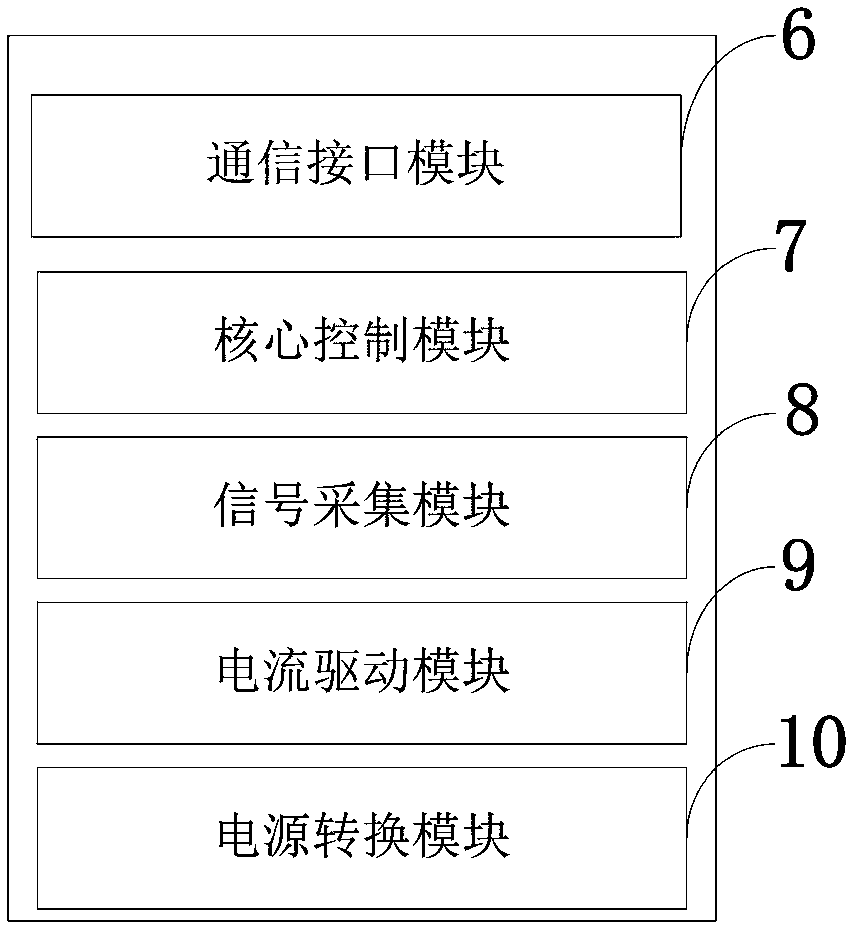
- Application Information
AI Technical Summary
Problems solved by technology
Method used
Image

Examples
Embodiment Construction
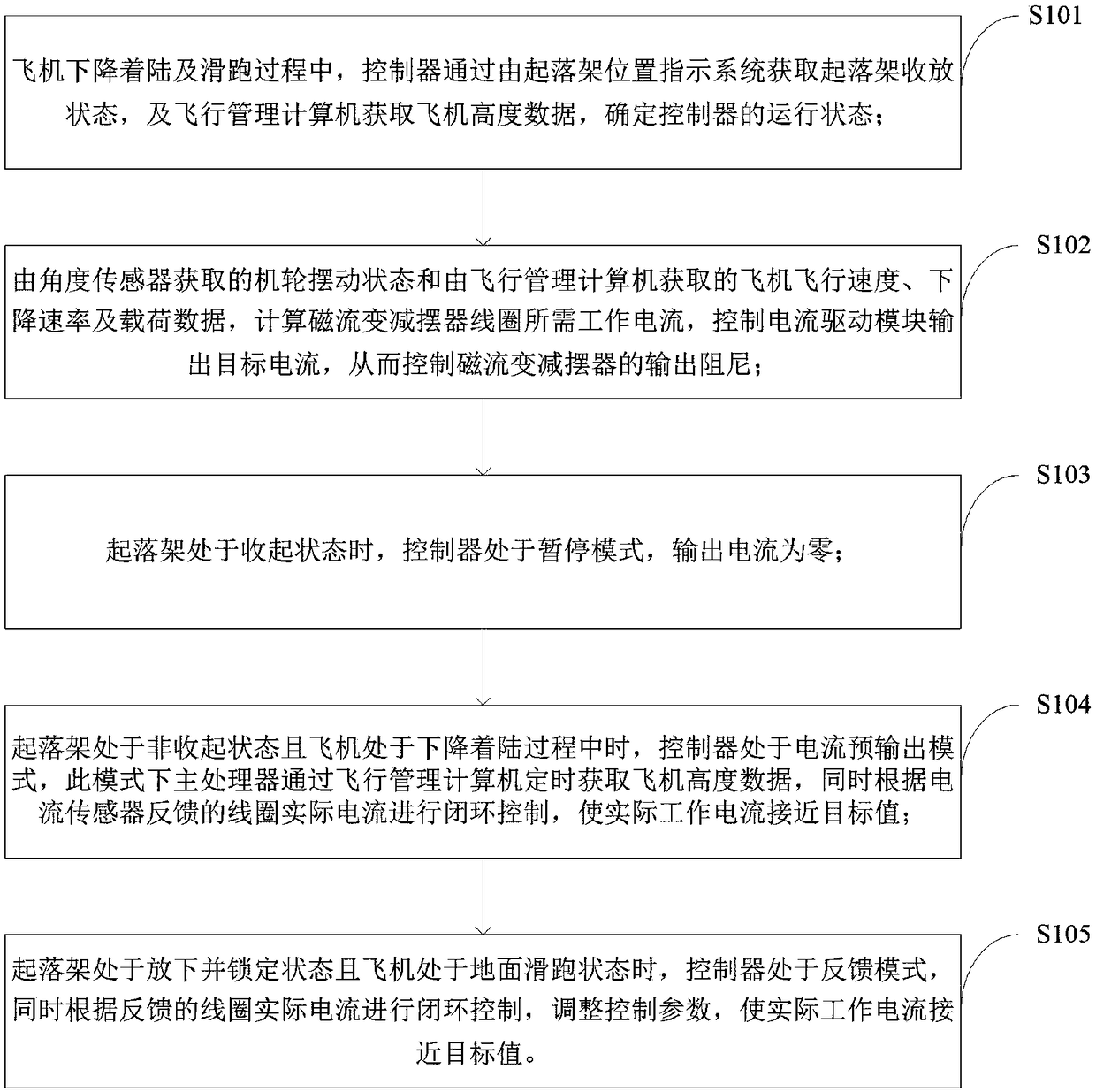
[0042] In order to make the object, technical solution and advantages of the present invention more clear, the present invention will be further described in detail below in conjunction with the examples. It should be understood that the specific embodiments described here are only used to explain the present invention, not to limit the present invention.
[0043] The invention aims to solve the problem that the existing shimmy reducer can only reduce the pendulum array passively by consuming energy, the damping working range is narrow, the damping force cannot be adjusted in real time according to the swing state of the landing gear, and the oil viscosity is affected by temperature and oil compression Obvious effect; the existing shimmy absorber has complex structure, limited control effect, poor control accuracy, and high power consumption technical problems. It is possible to provide real-time adjustment of the damping force of the magneto-rheological shimmy damper according...
PUM
 Abstract
Description
Claims
Application Information