
Reverse tail spin installation device and positioning method

An installation device, installation and positioning technology, applied in the field of aviation anti-spin, can solve the problems that cannot meet the rapid response requirements of modern aircraft, the difficulty of accurate positioning and installation of anti-spin devices, the self-weight deformation of tooling cantilever, etc., to meet the requirements of rapid response , Small error, small laser divergence effect

Inactive Publication Date: 2018-11-13
CHENGDU AIRCRAFT INDUSTRY GROUP
View PDF7 Cites 0 Cited by
  • Summary
  • Abstract
  • Description
  • Claims
  • Application Information

AI Technical Summary

Problems solved by technology

However, the anti-spin device is far away from the airframe and belongs to the long cantilever over-positioning structure. In aircraft modification, it is extremely difficult to accurately locate and install the anti-spin device. Design the assembly frame to locate the anti-spin device, or select the important structural holes of the fuselage (generally choose the fuselage-vertical tail connection hole) as the reference, and extend a rigid structure to locate the umbrella bracket
[0004] Of the above two methods, the former is costly and has a long cycle, which cannot meet the rapid response requirements of modern aircraft; although the cost and cycle of the latter are improved compared with the former, but due to the deformation of the tooling cantilever and the error of the aircraft itself, the accuracy is low

Method used


Image

  • Reverse tail spin installation device and positioning method
  • Reverse tail spin installation device and positioning method
  • Reverse tail spin installation device and positioning method

Examples


Embodiment 1

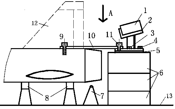
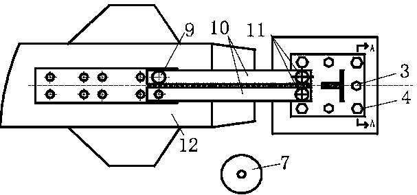
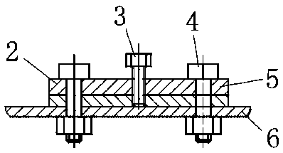
[0033] Such as Figures 1 to 3 As shown, an anti-spin installation device includes an anti-spin device 1 and a tail 12, one end of a positioning rod 10 is connected to the tail 12 through a first positioning pin 9, and the other end of the positioning rod 10 The support seat 2 is connected with the second positioning pin 11, the upper end of the support seat 2 is fixed with the anti-tail spin device 1, the lower end is connected with the base 6 through the fastening bolt 4, and the support frame 9 is installed at the lower end of the tail 12, so A digitized measuring device 7 is arranged beside the support frame 9 .

[0034] Connect the tail 12 and the anti-spin device 1 through the positioning rod 10, the first positioning pin 9 fixes one end of the positioning rod 10 on the tail 12, and the second positioning pin 9 fixes the support base 2 on the positioning rod 10 the other end of the tail, so that the anti-spin device 1 can be quickly and conveniently installed on the tai...

Embodiment 2

[0036] Such as Figures 1 to 3 As shown, an anti-spin installation device includes an anti-spin device 1 and a tail 12, one end of a positioning rod 10 is connected to the tail 12 through a first positioning pin 9, and the other end of the positioning rod 10 The support seat 2 is connected with the second positioning pin 11, the upper end of the support seat 2 is fixed with the anti-tail spin device 1, the lower end is connected with the base 6 through the fastening bolt 4, and the support frame 9 is installed at the lower end of the tail 12, so A digitized measuring device 7 is arranged beside the support frame 9 .

[0037] A backing plate 5 is arranged between the supporting base 2 and the base 6, and the supporting base 2 is fixed with the backing plate 5 by adjusting bolts 3, and the adjusting bolts 3 and the fastening bolts 4 are four and evenly distributed.

[0038] The backing plate 5 is made of epoxy resin material.

[0039] Connect the tail 12 and the anti-spin devi...

Embodiment 3

[0043] Such as Figures 1 to 3 As shown, an anti-spin installation device includes an anti-spin device 1 and a tail 12, one end of a positioning rod 10 is connected to the tail 12 through a first positioning pin 9, and the other end of the positioning rod 10 The support seat 2 is connected with the second positioning pin 11, the upper end of the support seat 2 is fixed with the anti-tail spin device 1, the lower end is connected with the base 6 through the fastening bolt 4, and the support frame 9 is installed at the lower end of the tail 12, so A digitized measuring device 7 is arranged beside the support frame 9 .

[0044] A backing plate 5 is arranged between the supporting base 2 and the base 6, and the supporting base 2 is fixed with the backing plate 5 by adjusting bolts 3, and the adjusting bolts 3 and the fastening bolts 4 are four and evenly distributed.

[0045] The backing plate 5 is made of epoxy resin material.

[0046] The digital measuring device 7 is a laser ...


PUM


Abstract

The invention relates to a reverse tail spin installation device and a positioning method. The reverse tail spin installation device comprises a reverse tail spin device and an aircraft tail. The aircraft tail is connected with one ends of positioning rods by first positioning pins. The other ends of the positioning rods are connected with a supporting seat by second positioning pins. The reversetail spin device is fixed to upper end of the supporting seat. The lower end of the supporting seat is connected with a base by fastening bolts. Supporting brackets are mounted on the lower end of theaircraft tail. A digital measuring device is arranged beside the supporting brackets. The aircraft tail and the reverse tail spin device are connected by the positioning rods. One ends of the positioning rods are fixed to the aircraft tail by the first positioning pins, and the supporting seat is fixed to the other ends of the positioning rods by the second positioning pins, and therefore the reverse tail spin device being mounted at the aircraft tail quickly and conveniently is achieved, and the cost is low. Through cooperation of the digital measuring device and the base, the height of thebase can be adjusted, and therefore accurate installation of the reverse tail spin device is achieved.

Description

technical field [0001] The invention belongs to the technical field of aviation anti-spin, and in particular relates to an anti-spin installation device and a positioning method. Background technique [0002] High angle of attack and post-stall flight are very complicated and dangerous flight verification items, and the aircraft is very easy to enter a spin state, which may lead to flight accidents. In order to ensure the flight safety of the aircraft after a stall, modern aircraft generally adopt the method of installing an anti-spin device to provide a method for the aircraft to recover from the flight state of the spin to ensure high angle of attack and flight safety after the stall verification. [0003] In modern aircraft, two methods are usually used: first, the design generally adopts a four-bar support cantilever structure, and the anti-spin device is hovered above the rear of the engine exhaust. After the aircraft will enter the spin, the aircraft will deviate from...

Claims


Application Information

Patent Timeline
Patent Type & Authority Applications(China)
IPC IPC(8): B64F5/10
CPCB64F5/10
Inventor 陶西慧刘克非张立新温晓燕谭明威沈聪冒朝东
Owner CHENGDU AIRCRAFT INDUSTRY GROUP
Learn More