
Water cushion slope-shifting height adjustable counterweight dam

A technology of water pads and water-facing slopes, applied in water conservancy projects, sea area projects, buildings, etc., can solve problems such as high construction requirements, blockage of diversion channels, failure to achieve expected control effects, etc., and achieve high overall stability and convenience transport effect

Inactive Publication Date: 2020-05-15
XIANGSHAN XINGQI ELECTRICAL APPLIANCE TECH
View PDF5 Cites 0 Cited by
  • Summary
  • Abstract
  • Description
  • Claims
  • Application Information

AI Technical Summary

Problems solved by technology

[0003] However, the debris flow is mixed with a large number of stones and trees during its movement, which can easily block the diversion channels of conventional debris flow dams, etc., resulting in the accumulation of debris flow
Under complex geological environment conditions, the gravity retaining wall bears special and changeable loads. Once the dam collapses during the debris flow outbreak, it will not only fail to achieve the expected prevention and control effect, but also the dam body and the solid materials it blocks will also be damaged. It will become the source of loose solid matter for debris flow, directly participate in the movement of debris flow, increase the flow and destructiveness of debris flow, and may even cause more unexpected disaster losses
[0004] Due to the sudden occurrence of debris flow and the certainty of the level of debris flow, it is difficult for a single method of prevention and control of debris flow to meet the different levels of debris flow prevention and control.
If a large and stable retaining dam is built, it can effectively solve the problem of block impact damage of traditional retaining dams to a large extent, but the construction requirements are high, the construction is difficult and the cost is doubled, and large-scale construction cannot be achieved.

Method used


Image

  • Water cushion slope-shifting height adjustable counterweight dam
  • Water cushion slope-shifting height adjustable counterweight dam
  • Water cushion slope-shifting height adjustable counterweight dam

Examples


Embodiment 1

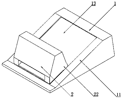
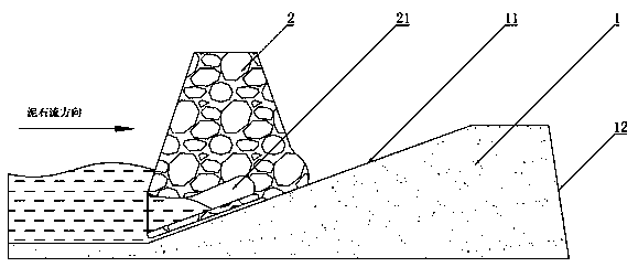
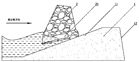
[0043] Such as Figure 1 ~ Figure 4 As shown, a water cushion slope-shifting height-adjustable counterweight dam described in Embodiment 1 includes a base dam body 1 and a mobile dam 2 . The mobile dam 2 is movably arranged on the base plate, and under the impact of the debris flow, the mobile dam 2 is moved upwards, allowing more space to resist the debris flow and buffer the impact of the debris flow.

[0044] Wherein, the foundation dam body 1 is formed by pouring steel beams and concrete. The base dam body 1 is provided with a facing slope 11 and a backwater slope 12 corresponding to each other, and the cross section of the foundation dam body 1 is trapezoidal. The facing slope 11 is a side wall that bears the impact of debris flow, but its slope is relatively gentle, while the slope of the backwater slope 12 is relatively steep.

[0045] The mobile dam 2 is cast from steel beams and concrete with a strength higher than C40, and its bottom surface matches the water-facin...

Embodiment 2

[0052] Such as Figure 5 ~ Figure 7 As shown, the water cushion slope-shifting height adjustable counterweight dam described in Embodiment 2 is similar to the structure of Embodiment 1, the difference is that the supporting protrusion is specifically a rear wheel, and the guide rail 13 matches the Describe the rear wheel.

[0053] Specifically, two rear wheels are hinged at the bottom rear end of the mobile dam 2 through a steel shaft, and the rear wheels are embedded and hinged at the bottom of the mobile dam 2 . The rear wheel is placed in a prototype steel barrel through a steel beam, and poured concrete is solidified.

[0054] The water-facing slope 11 is recessed to form a set of guide rails 13 parallel to each other. The guide rail 13 matches the rear wheel, and the upward movement of the limit mobile dam 2 has a guiding effect on the rear wheel. The embedded rear wheel is combined with the concave guide rail 13, so that the bottom surface of the mobile dam 2 is more ...

Embodiment 3

[0057] Such as Figure 8 ~ Figure 9 As shown, the water cushion slope-shifting height adjustable counterweight dam described in Embodiment 3 is similar to the structure of Embodiment 1, the difference is that the water cushion chamber 21 of Embodiment 3 includes a front chamber 211 and a rear chamber 212 , the front chamber 211 communicates with the rear chamber 212 through a restrictor 213 .

[0058] Specifically, the middle part of the water pad container 21 protrudes to form a convex edge, and the convex edge separates the water pad container 21 into a front cavity 211 and a rear cavity 212 . The front chamber 211 and the rear chamber 212 are arranged side by side sequentially from the opening of the water cushion chamber 21 . The distance between the convex edge and the inner wall forms a restrictor opening 213 , so that the front chamber 211 communicates with the rear chamber 212 .

[0059] The opening of the front chamber 211 is the opening of the water cushion chamber...


PUM


Abstract

The invention discloses a water pillow slope moving type heightening adjustable balance weight dam which comprises a base dam body and a moving dam. The base dam body comprises an upstream slope and adownstream slope which correspond to each other; and the moving dam is placed on the upstream slope, the bottom of the moving dam is hollow to form a water pillow containing cavity with an opening, debris flow enters the water pillow containing cavity from an opening of the water pillow containing cavity, and a supporting protrusion is arranged at the back end of the bottom of the moving dam. Thefront end of the bottom of the moving dam is heightened through impact of the debris flow, and the moving dam moves on the upstream slope under assistance of the supporting protrusion. Large space isavoided by upward moving heightening and retreating of the moving dam for containing the debris flow.

Description

technical field [0001] The invention belongs to the technical field of debris flow safety protection, and in particular relates to a water cushion slope-shifting height adjustable counterweight dam. Background technique [0002] The dynamic pressure of mud-rock fluid slurry and the impact force of rocks are typical impact loads, which are characterized by a short action time (mostly measured in milliseconds, microseconds or even nanoseconds), but will generate extremely high pressure, eventually causing the medium Movement, material failure, and failure of entire structures. At present, the main means of preventing debris flow is to build debris flow retaining dams, adopt gravity retaining walls to completely block debris flows, and add diversion channels on the basis of the retaining dams to buffer the impact of debris flows. [0003] However, during the movement of debris flow, a large number of stones and trees are mixed, which can easily block the diversion channels of ...

Claims


Application Information

Patent Timeline
Patent Type & Authority Patents(China)
IPC IPC(8): E02B7/00
CPCE02B7/00
Inventor 不公告发明人
Owner XIANGSHAN XINGQI ELECTRICAL APPLIANCE TECH
Learn More