
Drying device for heat insulation plate

A technology of drying device and thermal insulation board, which is applied in drying, dryer, heating device and other directions, can solve the problems of unfavorable thermal insulation board heat exchange drying work, residual thermal insulation board, waste of energy, etc., to increase the effective effect. The effect of reducing the contact area and improving the drying efficiency

Inactive Publication Date: 2018-11-13
吴江市金搏保温材料厂(普通合伙)
View PDF1 Cites 7 Cited by
  • Summary
  • Abstract
  • Description
  • Claims
  • Application Information

AI Technical Summary

Problems solved by technology

[0004] However, during the microwave heating process of this device, a large amount of heat will be generated and directly emitted into the atmosphere, which not only wastes a lot of energy, but also has a certain impact on the environment; this device directly places the insulation board on the large track plane It is not conducive to heat exchange and drying between the bottom of the insulation board and the air, resulting in moisture residue at the bottom of the insulation board. For this reason, we propose a drying device for insulation boards

Method used

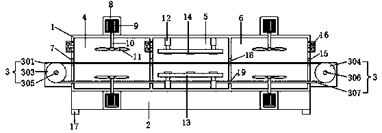
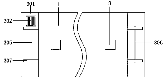
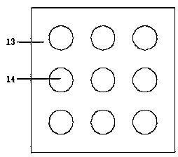

Image

  • Drying device for heat insulation plate
  • Drying device for heat insulation plate
  • Drying device for heat insulation plate

Examples


Embodiment Construction

[0019] The following will clearly and completely describe the technical solutions in the embodiments of the present invention with reference to the accompanying drawings in the embodiments of the present invention. Obviously, the described embodiments are only some, not all, embodiments of the present invention. Based on the embodiments of the present invention, all other embodiments obtained by persons of ordinary skill in the art without making creative efforts belong to the protection scope of the present invention.

[0020] In describing the present invention, it should be understood that the terms "upper", "lower", "front", "rear", "left", "right", "top", "bottom", "inner", " The orientation or positional relationship indicated by "outside", etc. is based on the orientation or positional relationship shown in the drawings, and is only for the convenience of describing the present invention and simplifying the description, rather than indicating or implying that the referre...


PUM


Abstract

The invention discloses a drying device for a heat insulation plate. The drying device includes a box body, a base and a transmission mechanism; the box body is located at the top of the base, an inner cavity of the box body is divided into a pre-drying room, a drying room and a heat dissipation room through a partition plate, a feeding opening is formed in the left side wall of the pre-drying room, a discharging opening is formed in the right side wall of the heat dissipation room, motor boxes are arranged in the top of the box body and the base, a heat dissipation motor is arranged in an inner cavity of each motor box, and a rotating shaft is arranged at the power output end of each heat dissipation motor; and a fan blade is arranged at the end, located in the inner cavity of the box body, of each rotating shaft, electric telescopic rods are symmetrically arranged at the top and the bottom of the inner cavity of the drying room, base seats are arranged on the side, attached to each other, of the two sets of electric telescopic rods, microwave generators are arranged on the sides, attached to each other, of the base seats, heat exchange fans are arranged on the left and right sidewalls of the pre-drying room and the right side wall of the heat dissipation room, and a supporting column is arranged in the base. The drying device can reuse the heat discharged by electromagneticheating to dry the heat insulation plate for the first time, the drying effect is better, and the energy is saved.

Description

technical field [0001] The invention relates to the technical field of heat preservation board processing, in particular to a heat preservation board drying device. Background technique [0002] The thermal insulation board is made of polystyrene resin as raw material plus other raw and auxiliary materials and polymers. After heating and mixing, the catalyst is injected at the same time, and then extruded to form a rigid foam plastic board. It has moisture-proof and waterproof properties. Due to the price of the thermal insulation board Affordable, the use of insulation boards is increasing continuously, and during the production and processing of insulation boards, it is necessary to dry and shape the insulation boards. [0003] The application number is 201721280626.8, and the patent name is a new type of multifunctional polystyrene insulation board microwave drying equipment, including the main body of the drying chamber, the base, the transmission motor, the baffle, the ...

Claims


Application Information

Patent Timeline
Patent Type & Authority Applications(China)
IPC IPC(8): F26B15/04F26B21/00F26B23/08F26B25/00
CPCF26B15/04F26B3/347F26B21/004F26B25/009
Inventor 张金根
Owner 吴江市金搏保温材料厂(普通合伙)
Learn More