Eureka AIR delivers breakthrough ideas for toughest innovation challenges, trusted by R&D personnel around the world.

Cantilever beam theory-based fiber bragg grating wing deformation measurement modeling and calibration method

A cantilever beam theory and fiber grating technology, applied in the field of aerial remote sensing, can solve the problems that affect the accuracy of InSAR interferometric imaging, baseline measurement error, and difficulty in flexible change process

Active Publication Date: 2018-11-13
BEIHANG UNIV
View PDF6 Cites 18 Cited by
  • Summary
  • Abstract
  • Description
  • Claims
  • Application Information

AI Technical Summary

Problems solved by technology

However, since the flexible change process of the baseline between the main and auxiliary antennas is difficult to accurately describe, the position and velocity information of the main POS cannot be accurately transmitted to the sub-IMU, resulting in measurement errors of the baseline, which in turn affects the accuracy of InSAR interferometric imaging.

Method used


Image

  • Cantilever beam theory-based fiber bragg grating wing deformation measurement modeling and calibration method
  • Cantilever beam theory-based fiber bragg grating wing deformation measurement modeling and calibration method
  • Cantilever beam theory-based fiber bragg grating wing deformation measurement modeling and calibration method

Examples


Embodiment 1

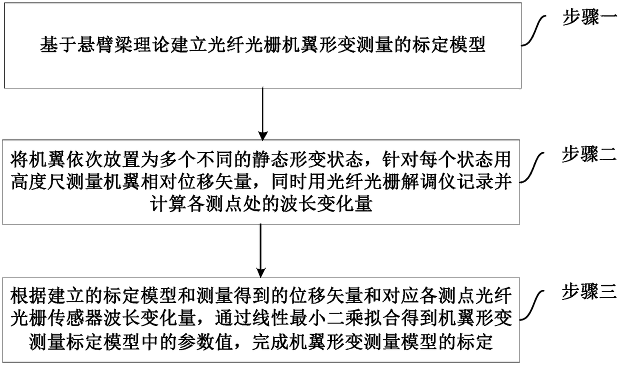
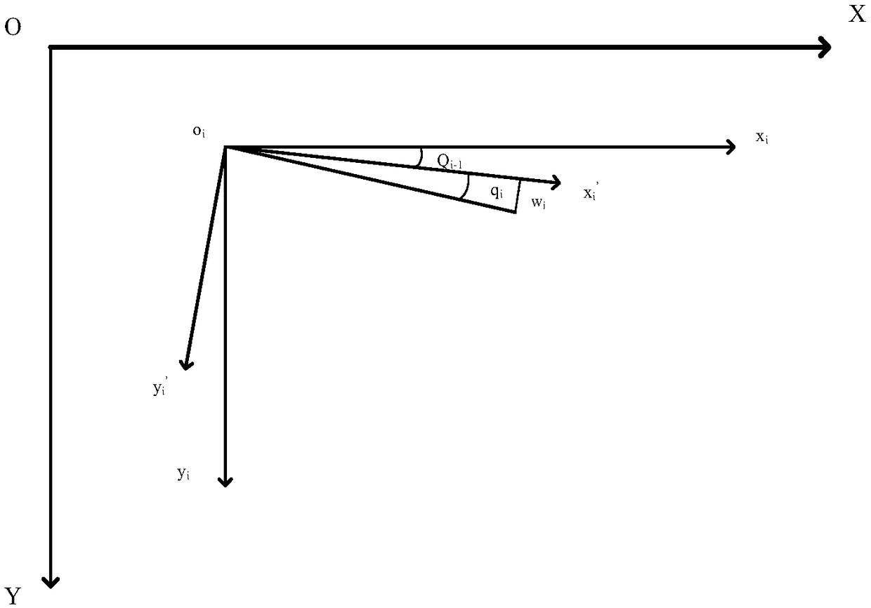
[0031] Embodiment 1 of the present invention provides a method for modeling and calibrating the deformation of an FBG wing based on the cantilever beam theory. A FBG sensor is pasted on the wing according to a predetermined fiber distribution scheme, and each measuring point is analyzed separately. By making the wing droop from the natural straight state, multiple deformation positions are selected to measure with the height gauge, and the relative displacement vector of the wing relative to the straight state is calculated, and at the same time, the corresponding values ​​are measured by the fiber grating demodulator. The wavelength variation of the fiber grating sensor at the measuring point. According to the established calibration model and the measured multiple sets of wing relative displacement vectors and the wavelength variation of each measuring point, the parameter values ​​in the wing deformation measurement calibration model are fitted by linear least squares. Spec...


PUM


Abstract

The invention discloses a cantilever beam theory-based fiber bragg grating wing deformation measurement modeling and calibration method. The method includes the following steps that: a fiber bragg grating wing deformation measurement calibration model is established based on the cantilever beam theory; a wing is arranged into a plurality of different static deformation states sequentially, the relative displacement vector of the wing is measured with a height gauge for each state, and at the same time, a fiber bragg grating demodulator is adopted to record and calculate a wavelength variationquantity at each measuring point; and parameter values in the wing deformation measurement calibration model can be obtained through linear least squares fitting, and the calibration of a wing deformation measurement model can be completed. With the method of the invention adopted, difficulty in accurately describing flexibility change of a baseline between the phase centers of a primary IMU (Inertial Measurement Unit) and a secondary IMU which is caused by the dynamic change of the baseline of the elastic deformation of the body structure of an aircraft can be eliminated; and a dynamic modelof the change of the flexible baseline with the time is not required to be established, after the wing deformation measurement model is calculated, and a wing deformation displacement vector can be obtained.

Description

technical field [0001] The invention relates to a fiber grating wing deformation measurement modeling and calibration method based on cantilever beam theory, which belongs to the technical field of aerial remote sensing and can be used for interferometric imaging of an airborne dual-antenna InSAR system based on high-precision distributed POS. Background technique [0002] Interferometric Synthetic Aperture Radar (InSAR) technology combines synthetic aperture radar with microwave interferometry, and uses the interferometric phase formed by two or more radar complex images under different viewing angles as the information source for inversion to obtain the surface 3D terrain and its change information. Dual-antenna InSAR consists of a main antenna and an auxiliary antenna. The measurement accuracy of the spatial displacement vector (baseline) between the phase centers of the main and auxiliary antennas is one of the key factors affecting the accuracy of InSAR interferometric ...

Claims


Application Information

Patent Timeline
IPC IPC(8): G01B11/16G01S13/90
CPCG01B11/165G01S13/9023
Inventor 房建成王博李建利卢兆兴叶文刘刚
Owner BEIHANG UNIV
Why Eureka
Eureka Blog
Learn More