
Test device and test method for testing performance of fiber composite grid material

A technology of material properties and testing devices, applied in the direction of measuring devices, analysis materials, preparation of test samples, etc., can solve the influence of the inability to test the strength of composite mesh materials, and the inability to fully reflect the composite mesh, etc. problems, achieve the effect of reducing the overall weight, strong operability and cost saving

Pending Publication Date: 2018-11-13
CENT RES INST OF BUILDING & CONSTR CO LTD MCC GRP +1
View PDF0 Cites 4 Cited by
  • Summary
  • Abstract
  • Description
  • Claims
  • Application Information

AI Technical Summary

Problems solved by technology

This test method can not only obtain the performance of a single rib in the composite grid, but cannot fully reflect the characteristics of the overall material performance of the composite grid, and cannot test the strength and existence of nodes in the composite grid. Influence on the Strength of Composite Mesh Material

Method used


Image

  • Test device and test method for testing performance of fiber composite grid material
  • Test device and test method for testing performance of fiber composite grid material
  • Test device and test method for testing performance of fiber composite grid material

Examples


Embodiment 1

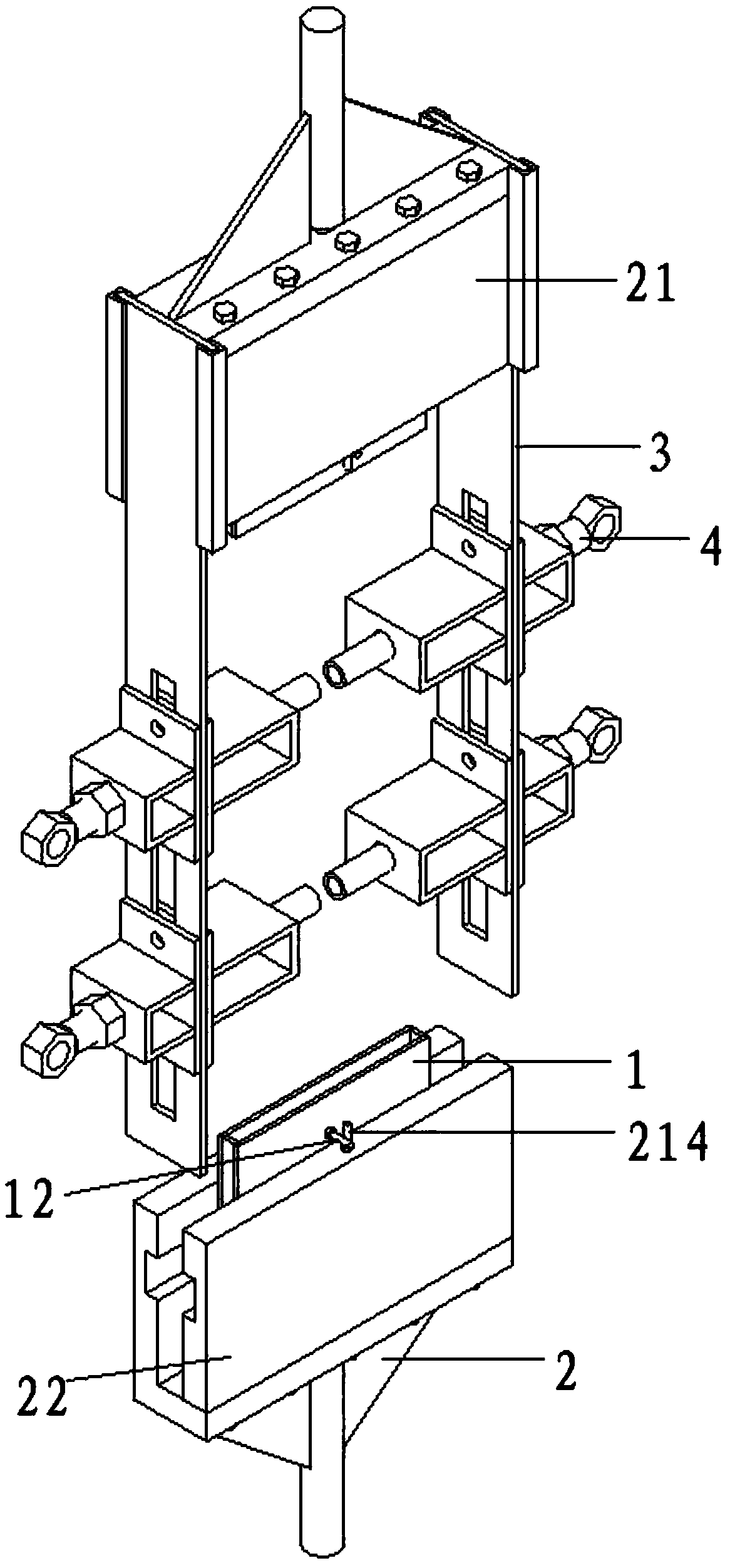
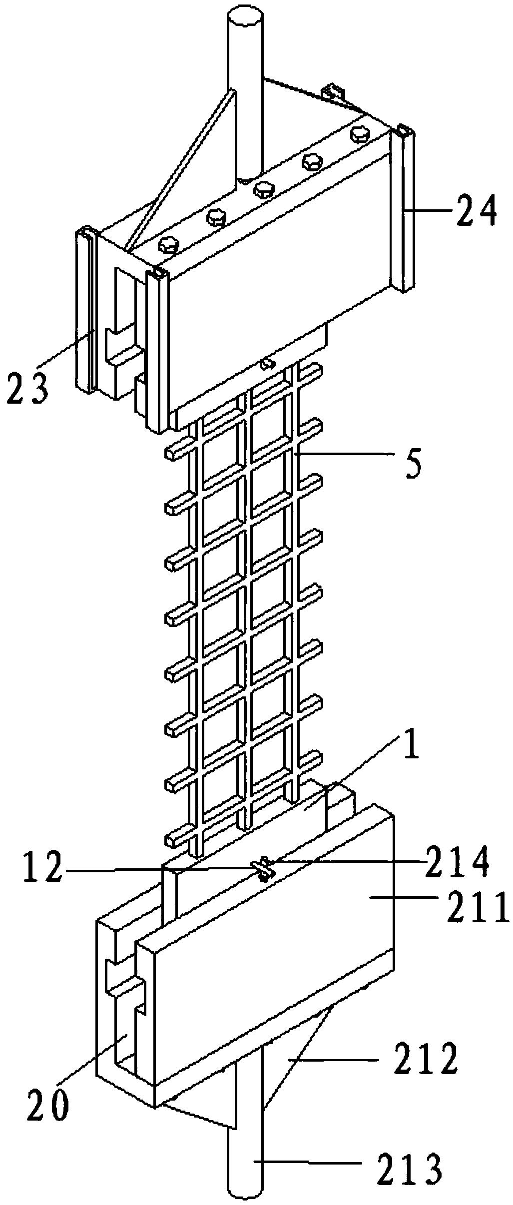
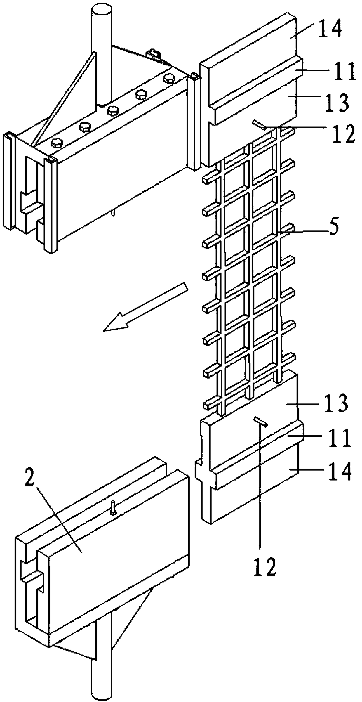
[0045] refer to Figure 1-2 , Embodiment 1 of the present invention discloses a test device for the performance of a fiber composite grid material, a composite grid fixture 1 and a clamping device 2; the clamping device 2 includes: an upper pair of pulling clamping devices 21 and a lower pair of clamping devices The pull clamping device 22, the upper pair of pull clamping device 21 and the lower pair of pull clamp device 22 are all provided with a chute-20, and the composite grid clamp 1 is connected with the upper pair of pull clamp device 21 and the lower pair of pull clamp device 20 through the chute-20 respectively. The lower clamping device 22 is slidingly connected; the top end of the upper clamping device 21 and the bottom end of the lower clamping device 22 are respectively clamped and connected with the upper and lower beams of the universal testing machine; between the composite grid clamps 1 Standard parts 5 are provided.

[0046] In order to further optimize the a...

Embodiment 2

[0056] refer to Figure 5 , Embodiment 2 of the present invention discloses a test device for the performance of a fiber composite grid material. On the basis of Embodiment 1, it also includes: 2 slidable steel plates 3 and 2 transverse rib fixing devices 4, which can The sliding steel plate 3 is arranged on both sides of the upper pair of clamping devices 21; the middle part of the sliding steel plate 3 is provided with a chute 2 31; the transverse rib fixing device 4 slides at any position on the chute 2 31 through the connector, and The transverse rib is fixedly connected with the slidable steel plate 3 through the connecting piece after the position of the second chute 31 is determined. The transverse ribs and nodes are constrained by the slidable steel plate 3 and the transverse rib fixing device 4, so as to realize the testing of the node strength and the influence of the node strength on the strength of the composite grid material.

[0057] In order to further optimize...

Embodiment 3

[0066] refer to Figure 9 , Embodiment 3 of the present invention discloses a test device for the performance of a fiber composite mesh material. On the basis of Embodiment 2, two transverse rib fixing devices are added and arranged oppositely.

[0067] refer to Figure 10-12 , the test method of embodiment 3 disclosed by the invention is:

[0068] Include the following steps:

[0069] S1. Select the appropriate steel plate to be welded as the composite grid fixture according to the grid size of the composite material and the type of test;

[0070] S2. Cut the composite material grid sample to be tested into a standard size to make a standard part. At least one end of the standard part is inserted into the center of the composite material grid fixture, and the glue is injected and anchored. After the glue is solidified, the composite material Grid fixture and standard parts become one;

[0071] S3. Slide the composite grid jig into the corresponding clamping device, and th...


PUM

PropertyMeasurementUnit
Diameteraaaaaaaaaa

Abstract

The invention discloses a test device and a test method for testing performance of a fiber composite grid material. The test device comprises composite grid fixtures and a clamping device, wherein theclamping device comprises an upper oppositely pulling clamping device and a lower oppositely pulling clamping device; sliding slots 1 are formed in the upper oppositely pulling clamping device and the lower oppositely pulling clamping device; the composite grid fixtures are connected to the upper oppositely pulling clamping device and the lower oppositely pulling clamping device in a sliding manner through the sliding slots 1 respectively; the top end of the upper oppositely pulling clamping device and the bottom end of the lower oppositely pulling clamping device are connected to an upper cross beam and a lower cross beam of a universal testing machine in a clamping manner respectively; a standard component is arranged between the composite grid fixtures; the test device further comprises slidable steel plates and transverse rib fixing devices. Through the test device and the test method for testing the performance of the fiber composite grid material, provided by the invention, an overall oppositely pulling test of multiple ribs of a fiber composite grid can be completed, the strength of joints can be tested and influence of the joints on the strength of the composite grid material can be tested; not only the working efficiency is improved, but also the test device can be reused, and thus the cost is saved.

Description

technical field [0001] The invention relates to the technical field of civil engineering material performance testing equipment, and more specifically relates to a testing device and a testing method for the performance of a fiber composite grid material. Background technique [0002] Fiber Reinforced Plastic (FRP) refers to a composite material formed by impregnating one or more high-performance continuous fibers such as carbon fiber, aramid fiber, high glass fiber, and basalt fiber in a resin with good corrosion resistance. , has the advantages of light weight, high strength, good durability, strong corrosion resistance, and strong designability. Fiber composite mesh is a new product form in fiber reinforced composite materials. In addition to the above advantages, its transverse and longitudinal ribs and nodes have high strength and stiffness. When the fiber composite grid is actually applied to the structure (reinforcement or new building), it is necessary to test the m...

Claims


Application Information

Patent Timeline
IPC IPC(8): G01N3/04G01N3/08G01N1/28
CPCG01N1/28G01N1/286G01N3/04G01N3/08G01N2001/2873G01N2203/0017Y02T50/40
Inventor 李荣邱红利胡乔陈文永丁一
Owner CENT RES INST OF BUILDING & CONSTR CO LTD MCC GRP
Learn More