Motion obstacle detection and positioning method based on depth images

A technology of obstacle detection and positioning method, which is applied in image enhancement, image analysis, image data processing, etc., and can solve problems such as difficult to operate quickly and efficiently, difficult to identify obstacles, etc.

Inactive Publication Date: 2018-11-13
HARBIN INST OF TECH
View PDF3 Cites 25 Cited by
  • Summary
  • Abstract
  • Description
  • Claims
  • Application Information

AI Technical Summary

Problems solved by technology

[0008] The present invention aims to solve the problems existing in existing obstacle detection methods that it is difficult to identify certain o

Method used


Image

  • Motion obstacle detection and positioning method based on depth images
  • Motion obstacle detection and positioning method based on depth images
  • Motion obstacle detection and positioning method based on depth images

Examples


specific Embodiment approach 1

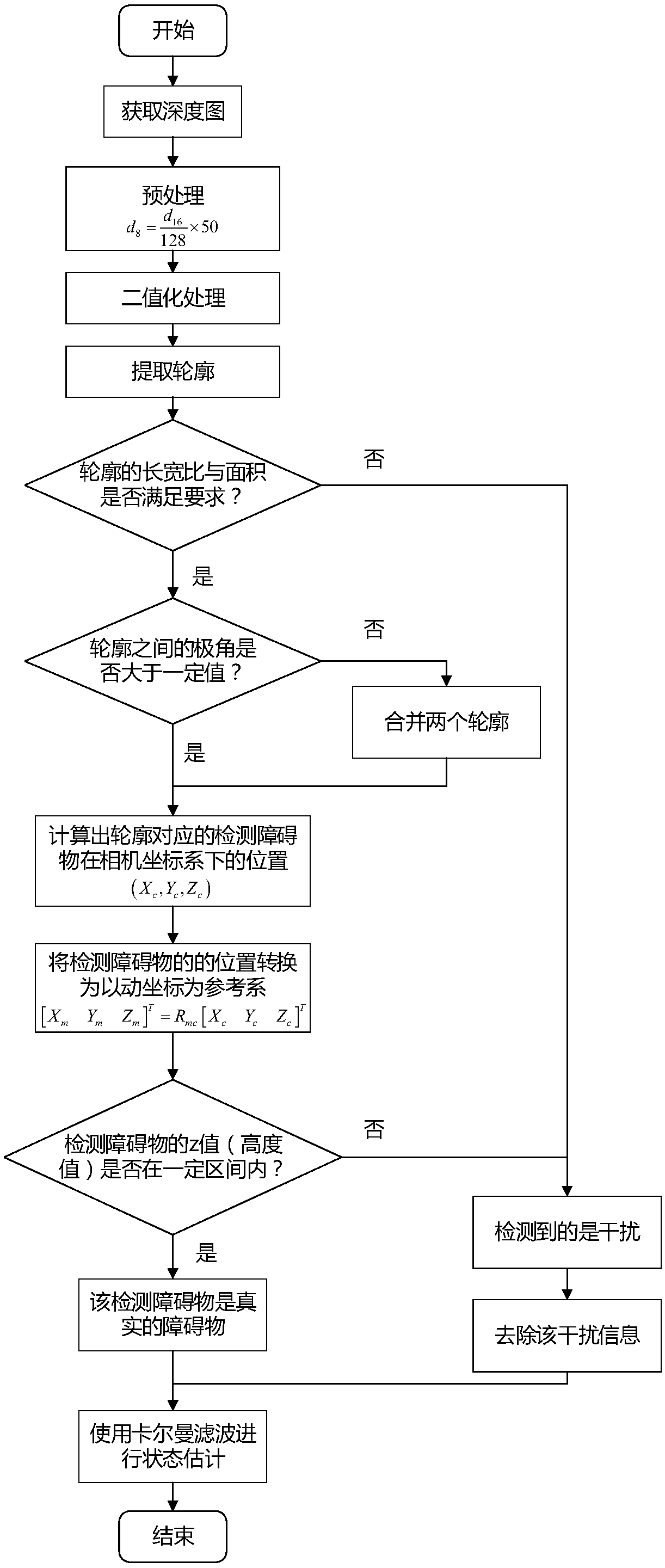
[0096] Specific implementation mode one: combine figure 1 Describe this embodiment, a method for detecting and locating a moving obstacle based on a depth map described in this embodiment includes the following steps:

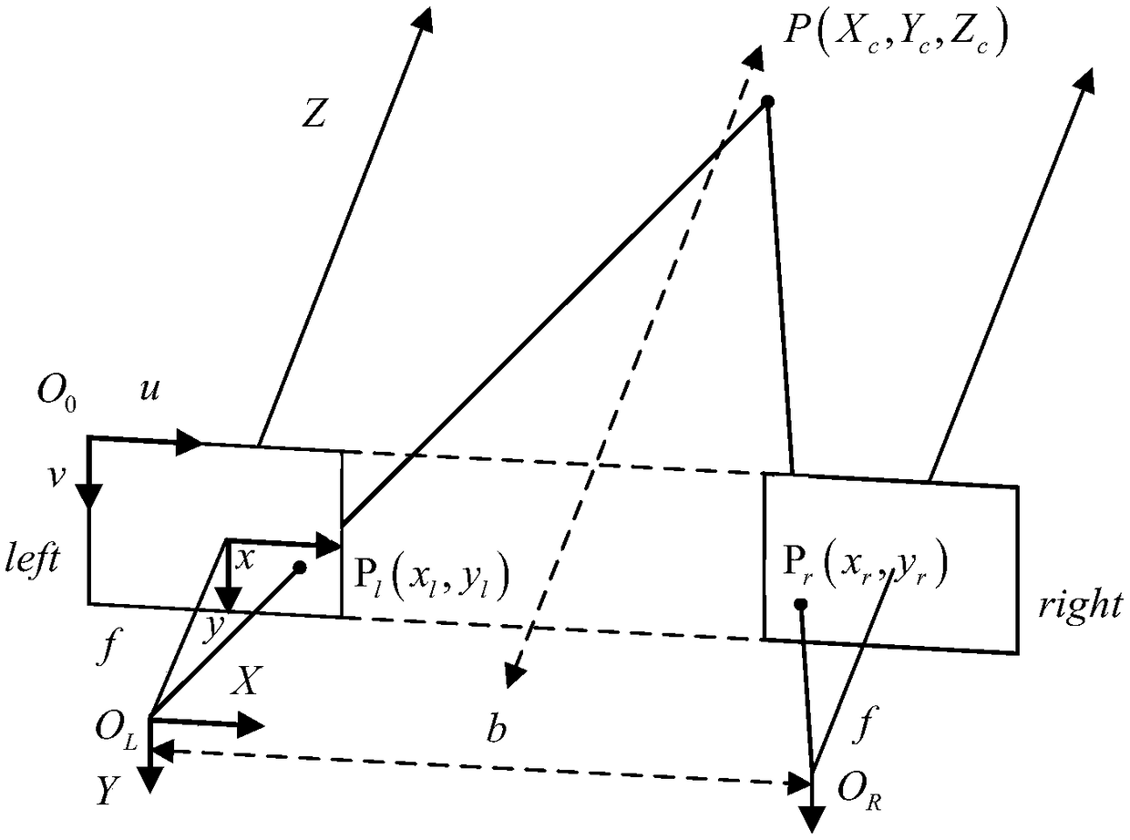
[0097] Step 1. Divide the eight cameras with the same focal length and the same internal parameters into four groups, two in each group, that is, four groups of binocular cameras are formed. Install four groups of binocular cameras on the front, rear, left and right directions of the quadrotor aircraft respectively. Configure each group of binocular cameras according to the parallel configuration method, and establish the imaging model of the flat configuration binocular cameras; figure 2 It is a schematic diagram of parallel configuration of binocular cameras.

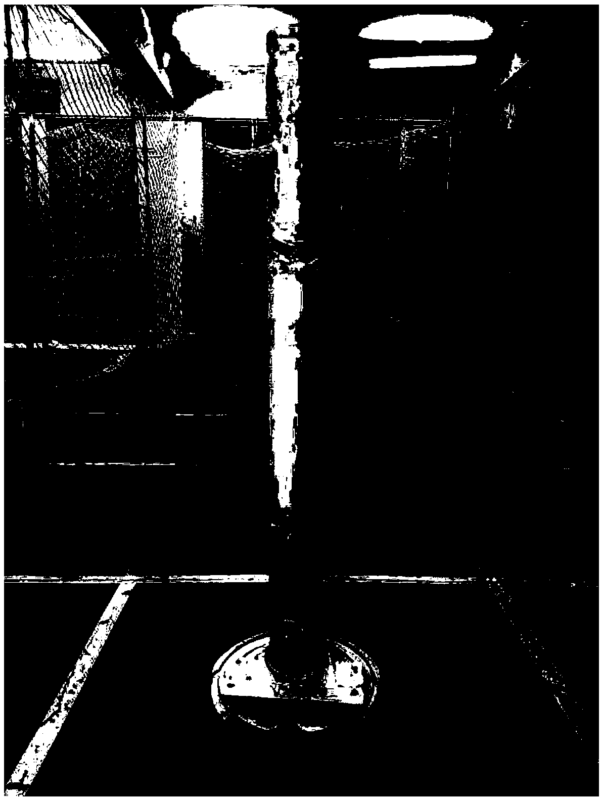
[0098] Step 2: The cameras collect video images at the same time, and obtain the depth map formed by each group of binocular cameras. And displayed in the form of grayscale image;

[0099] Step 3....

specific Embodiment approach 2

[0105] Specific implementation mode two: combination figure 2 To describe this embodiment,

[0106] The process of configuring each group of binocular cameras according to the parallel configuration described in step 1 of this embodiment includes the following steps:

[0107] Two cameras C1 and C2 with the same focal length and the same internal parameters are fixed in such a way that the optical axes are parallel to each other. Since the optical axis is perpendicular to the image plane, the y axes of the image coordinate systems of the two cameras are parallel to each other, and the x axes coincide with each other. It can be considered that a camera is completely coincident with another camera after being translated for a certain distance along its x-axis.

[0108] Other steps and parameters are the same as those in the first embodiment.

specific Embodiment approach 3

[0109] The process of establishing the imaging model of parallel configuration binocular cameras described in step 1 of this embodiment includes the following steps:

[0110] Firstly, determine the translation distance b that the two coordinate systems of the binocular cameras C1 and C2 configured in parallel differ only on the x-axis, which is the baseline length. Next assume that the coordinate system of C1 is O l x l Y l Z l , the coordinate system of C2 is O r x r Y r Z r , under the above camera configuration, the spatial point P(X c ,Y c ,Z c ) in the C1 coordinate system is (X l ,Y l ,Z l ), in the C2 coordinate system is (X l -b,Y r ,Z r ). Simultaneously assume that the image pixel coordinates of point P on the left camera image plane and the right camera image plane are (u 1 ,v 1 ), (u 2 ,v 2 ). According to the characteristics of the parallel configuration method, v 1 =v 2 , let the parallax d=u 1 -u 2 . According to the geometric relations...


PUM


Abstract

The invention discloses a motion obstacle detection and positioning method based on depth images and relates to a motion obstacle detection and positioning method based on binocular vision depth images. The method aims to solve the problems of an existing vision-based obstacle detection and positioning method that the calculation amount is large, instantaneity is poor, and it is difficult to distinguish obstacles and surroundings with similar image features. According to the method, the depth images are collected through binocular cameras configured in parallel, and denoising, binarization andother processing are performed on the depth images to obtain contours of candidate obstacles in the images; then the locations of the candidate obstacles are transferred into a local geographic coordinate system, and specific location interference is removed in combination with a spatial location relation; and a Kalman filtering mode is used to estimate the motion states of the obstacles so as toimprove the positioning accuracy of the obstacles. The method is suitable for motion obstacle detection and positioning based on the binocular vision depth images.

Description

technical field [0001] The invention relates to the field of digital image processing and information fusion, in particular to a depth map processing method in binocular vision. Background technique [0002] A drone is an unmanned aircraft that flies by remote control or onboard control equipment. Since UAVs are not restricted by manned factors, they are usually smaller in size, more maneuverable, and cheaper in cost, so they have gradually become a research hotspot in recent years. According to different fuselage structures, UAVs can be divided into rotary-wing UAVs and fixed-wing UAVs. People such as V.Kumar have demonstrated that under the situation of small load, the maneuverability of orthogonal multi-rotor aircraft is better than other types of aircraft. [0003] As a representative of multi-rotor aircraft, quadrotor aircraft has received more and more attention. At the same time, the rapid development of sensor technology, computer technology and data processing te...

Claims


Application Information

Patent Timeline
IPC IPC(8): G06T7/246G06T7/292
CPCG06T2207/10016G06T7/246G06T7/292
Inventor 于庆涛贺风华姚郁姚昊迪马杰
Owner HARBIN INST OF TECH
Why Eureka
Try Eureka