Supercharge Your Innovation With Domain-Expert AI Agents!

Micro unmanned aerial vehicle monitoring and control device

A control device and UAV technology, applied in aircraft traffic control, multi-aircraft traffic management, traffic control system, etc., can solve the problem that signal attributes cannot recognize UAV measurement and control signals, and do not have azimuth and pitch two-dimensional direction finding capabilities , can not effectively solve the problems of micro drones, and achieve the effect of wide control range, strong positioning ability and fast detection speed

Active Publication Date: 2018-11-13
NO 54 INST OF CHINA ELECTRONICS SCI & TECH GRP
View PDF7 Cites 1 Cited by
  • Summary
  • Abstract
  • Description
  • Claims
  • Application Information

AI Technical Summary

Problems solved by technology

Traditional radio monitoring and direction-finding equipment can monitor the appearance of signals in the frequency domain, but they cannot clarify the signal properties and cannot identify whether it is a UAV measurement and control signal; Possess the ability to locate the flight controller; traditional control equipment and monitoring and direction-finding equipment are independent and cannot be linked in real time and efficiently
Therefore, the problem of "black flying" of micro UAVs cannot be effectively solved.

Method used


Image

  • Micro unmanned aerial vehicle monitoring and control device
  • Micro unmanned aerial vehicle monitoring and control device
  • Micro unmanned aerial vehicle monitoring and control device

Examples


Embodiment Construction

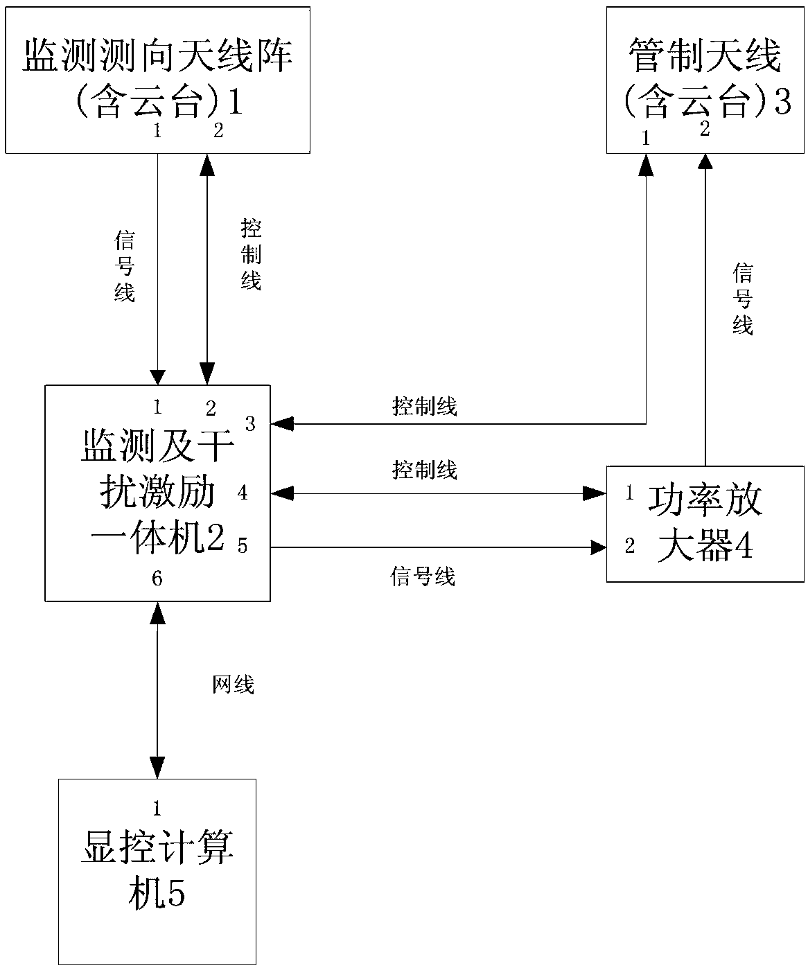
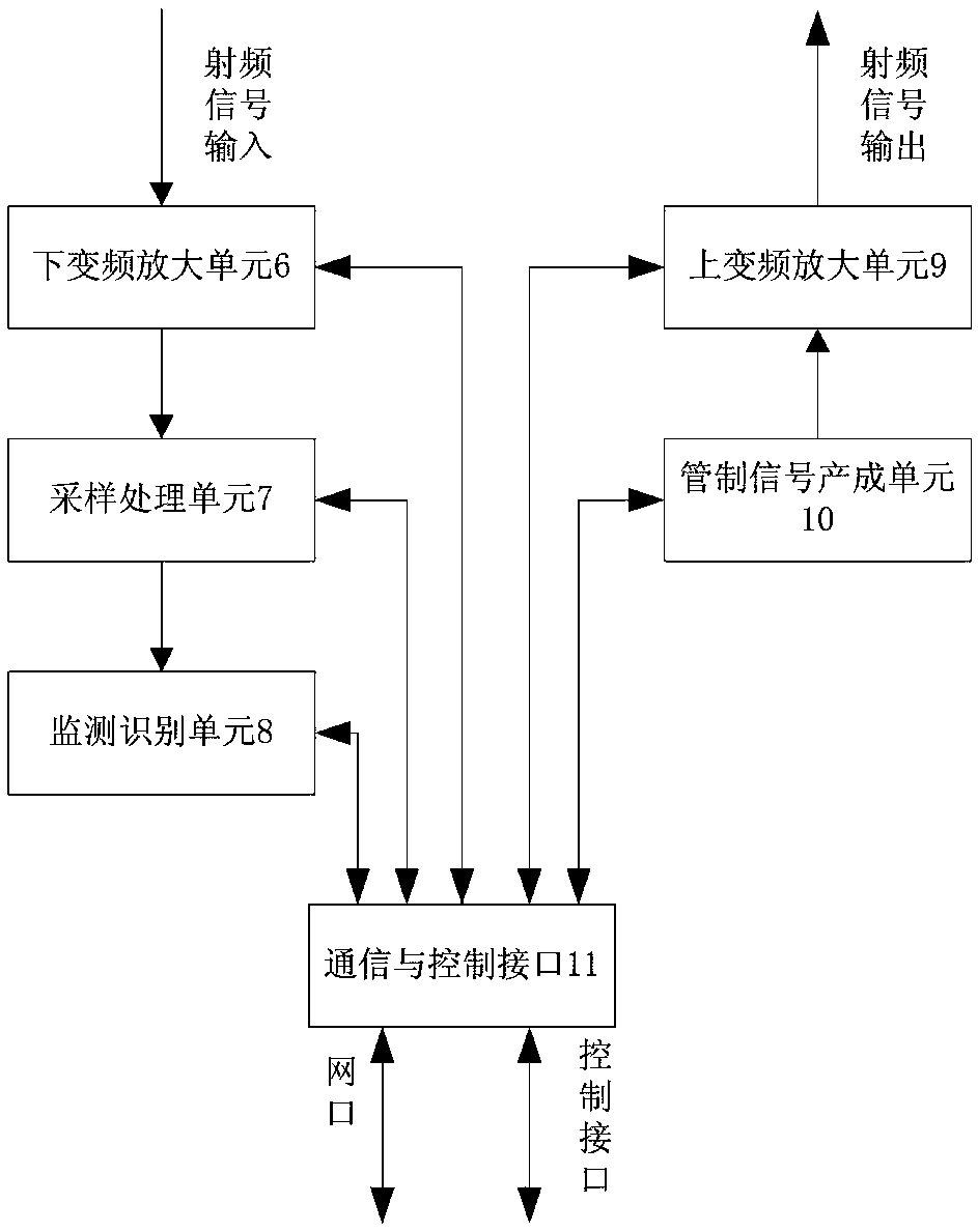
[0017] Below, combine figure 1 and figure 2 The present invention is further described.

[0018] refer to Figure 1 to Figure 2 , The present invention consists of a monitoring direction-finding antenna array (1), a monitoring and interference generating integrated machine (2), a control antenna (3), a power amplifier (4), and a display and control computer (5). figure 1 It is an electrical principle block diagram of the present invention, and the embodiment is according to figure 1 Connect the lines.

[0019] The monitoring and direction-finding antenna array (1) adopts a circularly polarized receiving antenna, which is convenient for receiving horizontally or vertically polarized signals of the UAV data link, and the antenna realizes signal monitoring and direction-finding through a five-element cross array. A flat spiral antenna is used, with a diameter of 50mm and a height of about 30mm. The gain above 2.4G can reach above 0dBm, and the maximum is about 4dBm.

[002...


PUM


Abstract

The invention discloses a micro unmanned aerial vehicle monitoring and control device, and relates to a device of discovering and identifying illegally flying micro unmanned aerial vehicle measurementand control signals and controlling the communication link of the illegally flying micro unmanned aerial vehicle in the fields of national defense, public security and radio monitoring. The micro unmanned aerial vehicle monitoring and control device comprises a monitoring and direction finding antenna array, an all-in-one machine of monitoring and interference generation, a power amplifier, a control antenna, a display control computer and other components. The micro unmanned aerial vehicle monitoring and control device adopts an unmanned aerial vehicle measurement and control signal detection and identification technology, a two dimension correlation interferometer direction finding technology, a single station positioning technology and a smart control signal generation technology, canrealize quick discovery and model identification of measurement and control signals of the unmanned aerial vehicle, can perform direction finding and positioning on the unmanned aerial vehicle and a light controller, can block the measurement and control link of the unmanned aerial vehicle, and can realize the effect of enabling the unmanned aerial vehicle to perform forced landing or return flight. The micro unmanned aerial vehicle monitoring and control device has the advantages of high integrity, high detection speed, high identification efficiency and the like, and can solve the problem ofearly discovery and efficiency control of illegally flying unmanned aerial vehicle.

Description

technical field [0001] The invention relates to a device for discovering and identifying the measurement and control signal of a "black flying" micro-drone and its communication link control in the fields of national defense, public safety and radio monitoring. Positioning of the controller. It is especially suitable for the protection of important places in the fields of national defense, public safety and radio monitoring, and the monitoring and control of illegal drones to ensure the safety of the airspace and frequency domain in the protected area. Background technique [0002] In recent years, the popularity of micro drones has become more and more widespread, but there are no effective management measures. Traditional radio monitoring and direction-finding equipment can monitor the appearance of signals in the frequency domain, but they cannot clarify the signal properties and cannot identify whether it is a UAV measurement and control signal; It has the ability to l...

Claims


Application Information

Patent Timeline
IPC IPC(8): G08G5/00H04K3/00G05B19/04
CPCG05B19/04G08G5/0043H04K3/82H04K2203/22
Inventor 牛景昌王志永黄好强程烨刘雷红杨伟周德强高杰朱路熊志广
Owner NO 54 INST OF CHINA ELECTRONICS SCI & TECH GRP
Features
  • R&D
  • Intellectual Property
  • Life Sciences
  • Materials
  • Tech Scout
  • Unparalleled Data Quality
  • Higher Quality Content
  • 60% Fewer Hallucinations
Learn More