
Physi-optics experiment platform

An experimental platform and physical optics technology, applied in teaching models, measuring devices, instruments, etc., can solve the problems that the experimental platform and equipment are difficult to meet the needs of use, large in size, inconvenient to move, etc., to achieve remote monitoring and remote control, structure Reasonable design, the effect of improving accuracy

Inactive Publication Date: 2018-11-13
HEZE UNIV
View PDF15 Cites 1 Cited by
  • Summary
  • Abstract
  • Description
  • Claims
  • Application Information

AI Technical Summary

Problems solved by technology

[0002] The optical experimental platform is widely used in the fields of optics, electronics, precision machinery manufacturing, metallurgy, aerospace, aviation, navigation, precision chemical industry and non-destructive testing, as well as precision experimental instruments and key devices for equipment vibration isolation in other mechanical industries. Among them, optical research In teaching and teaching, many important optical experiments such as light reflection, light refraction, plane mirror imaging, and convex lens imaging rules have high requirements for experimental equipment and experimental environments, and high measurement accuracy of experimental data. However, the existing experimental platforms and equipment are very difficult. Difficult to meet the needs of optical research or teaching experiments
[0003] The Chinese patent publication number is CN 105443931 A, and the name of the invention is a length-adjustable optical table instrument support. In the length-adjustable optical table instrument support, the first instrument placement table and the two second The instrument placement tables are slidingly connected separately, which can realize the characteristics of adjustable length, which has the advantages of convenient length adjustment, large adjustment range, and no swinging; in addition, assembly and maintenance are very convenient, but there is still a large volume. It is inconvenient to move, and the experimental data cannot be detected and stored in real time, and the influence of temperature and humidity in the air on the experimental results cannot be detected

Method used


Image

  • Physi-optics experiment platform
  • Physi-optics experiment platform
  • Physi-optics experiment platform

Examples


Embodiment 1

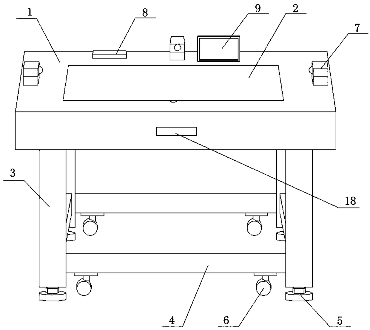
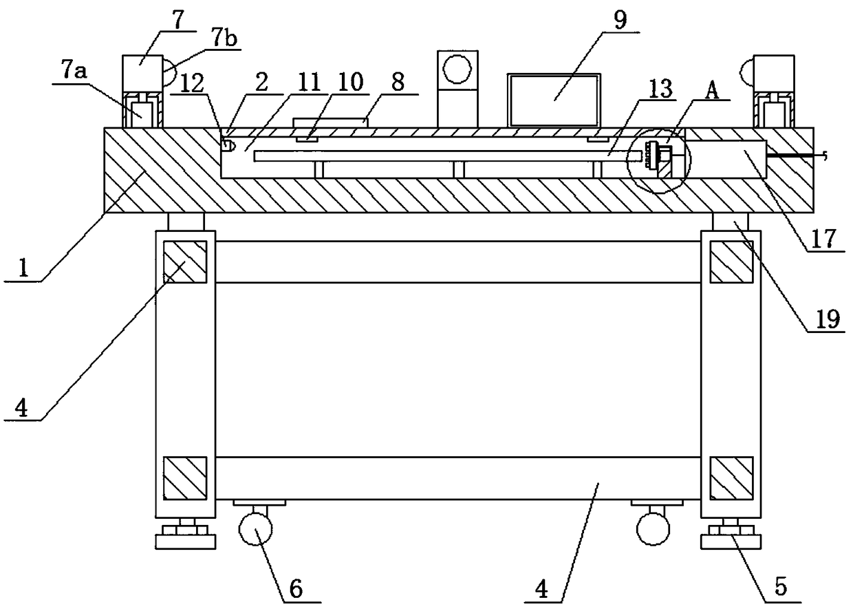
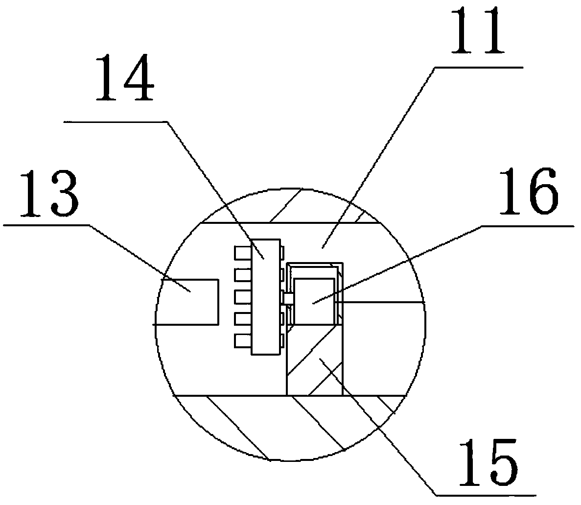
[0030] Embodiment 1: When carrying out the refraction experiment of light, turn the cover plate 2 upwards 90 degrees to open, place the required glass plate on the sliding rod 13 in the groove 11 and install the lamp tubes of different colors on the lamp holder, you can pass The GPRS module receives the remote control signal, and then the single-chip microcomputer notifies the rotating motor to rotate, so as to select the required light. After the light tube is turned on, the small camera on the side of the sliding rod 13 monitors the data of the experiment in real time, and the data collected by the monitoring can be passed through the controller 17. Send to display screen 9 and send to remote monitoring center and user's mobile phone through GPRS module 17e or bluetooth module 17f, realize long-distance monitoring.

Embodiment 2

[0031] Embodiment 2: When performing plane mirror imaging or convex lens imaging, adjust the base to make the platform surface level, and then place a plane mirror, light source or other tools on the platform surface to carry out the experiment. During the experiment, the monitoring device on the desktop 1 7 Real-time monitoring of the experimental situation on the platform, collecting and storing experimental data, and the monitoring device 7 can adjust the monitoring field of view through the electric telescopic column 7a below to meet the monitoring needs of the entire platform, and the data collected by monitoring can be passed through the controller 17 is sent to the display screen 9 and sent to the remote monitoring center and the user's mobile phone through the GPRS module 17e or the Bluetooth module 17f, so as to realize long and short distance monitoring.


PUM


Abstract

A physi-optics experiment platform comprises an experiment platform body consisting of a table top, a cover plate, support pillars, cross beams, adjusting bases and universal wheels, wherein three monitoring devices, a sensor group and a display screen are mounted above the table top, the three monitoring devices are mounted at the left end and the right end of the table top and at the rear end ofthe middle of the table top respectively, each monitoring device comprises an electric telescopic pillar and a camera, each electric telescopic pillar is mounted inside the bottom end of each monitoring device, one camera is mounted above each electric telescopic pillar, a camera lens of each camera faces the middle of the table top, the cover plate is mounted in the middle of the table top through hinges, and a groove is formed below the cover plate. By means of the groove, the universal wheels, the monitoring devices, the sensor group, a GPRS module and a Bluetooth module, movement after assembly is facilitated, real-time monitoring of the experiment condition is facilitated, the GPRS module and the Bluetooth module are used for transmitting or receiving remote and near control information, and the remote monitoring and remote operation functions are realized.

Description

technical field [0001] The invention relates to a physical optics experiment platform. Background technique [0002] The optical experimental platform is widely used in the fields of optics, electronics, precision machinery manufacturing, metallurgy, aerospace, aviation, navigation, precision chemical industry and non-destructive testing, as well as precision experimental instruments and key devices for equipment vibration isolation in other mechanical industries. Among them, optical research In teaching and teaching, many important optical experiments such as light reflection, light refraction, plane mirror imaging, and convex lens imaging rules have high requirements for experimental equipment and experimental environments, and high measurement accuracy of experimental data. However, the existing experimental platforms and equipment are very difficult. It is difficult to meet the needs of optical research or teaching experiments. [0003] The Chinese patent publication nu...

Claims


Application Information

Patent Timeline
Patent Type & Authority Applications(China)
IPC IPC(8): G09B23/22G01D21/02
CPCG09B23/22G01D21/02
Inventor 林蓉
Owner HEZE UNIV
Learn More