relay

A relay and frame technology, applied in the field of electrical control devices, can solve the problem of poor arc suppression effect of relays, and achieve the effects of sensitive relays, fast turn-on or turn-off speed, and lower gas temperature.

Active Publication Date: 2019-11-08
BYD CO LTD
View PDF8 Cites 1 Cited by
  • Summary
  • Abstract
  • Description
  • Claims
  • Application Information

AI Technical Summary

Problems solved by technology

[0005] The invention provides a relay to solve the problem of poor arc suppression effect of existing relays

Method used


Image

  • relay
  • relay
  • relay

Examples


Embodiment Construction

[0027] In order to have a clearer understanding of the technical features, purposes and effects of the present invention, the specific implementation manners of the present invention will now be described in detail with reference to the accompanying drawings.

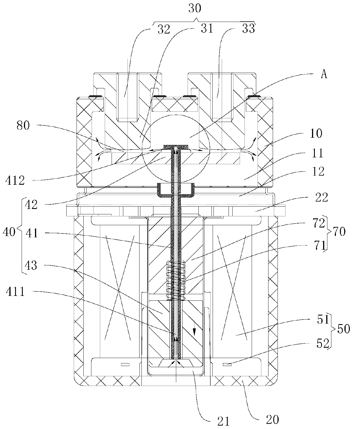
[0028] figure 1 The relay in this embodiment is shown. Such as figure 1 As shown, the relay includes a first frame body 10 , a second frame body 20 , an outlet assembly 30 , a push assembly 40 and a driving mechanism, wherein the driving mechanism includes a magnetic circuit assembly 50 and a reset assembly 70 .

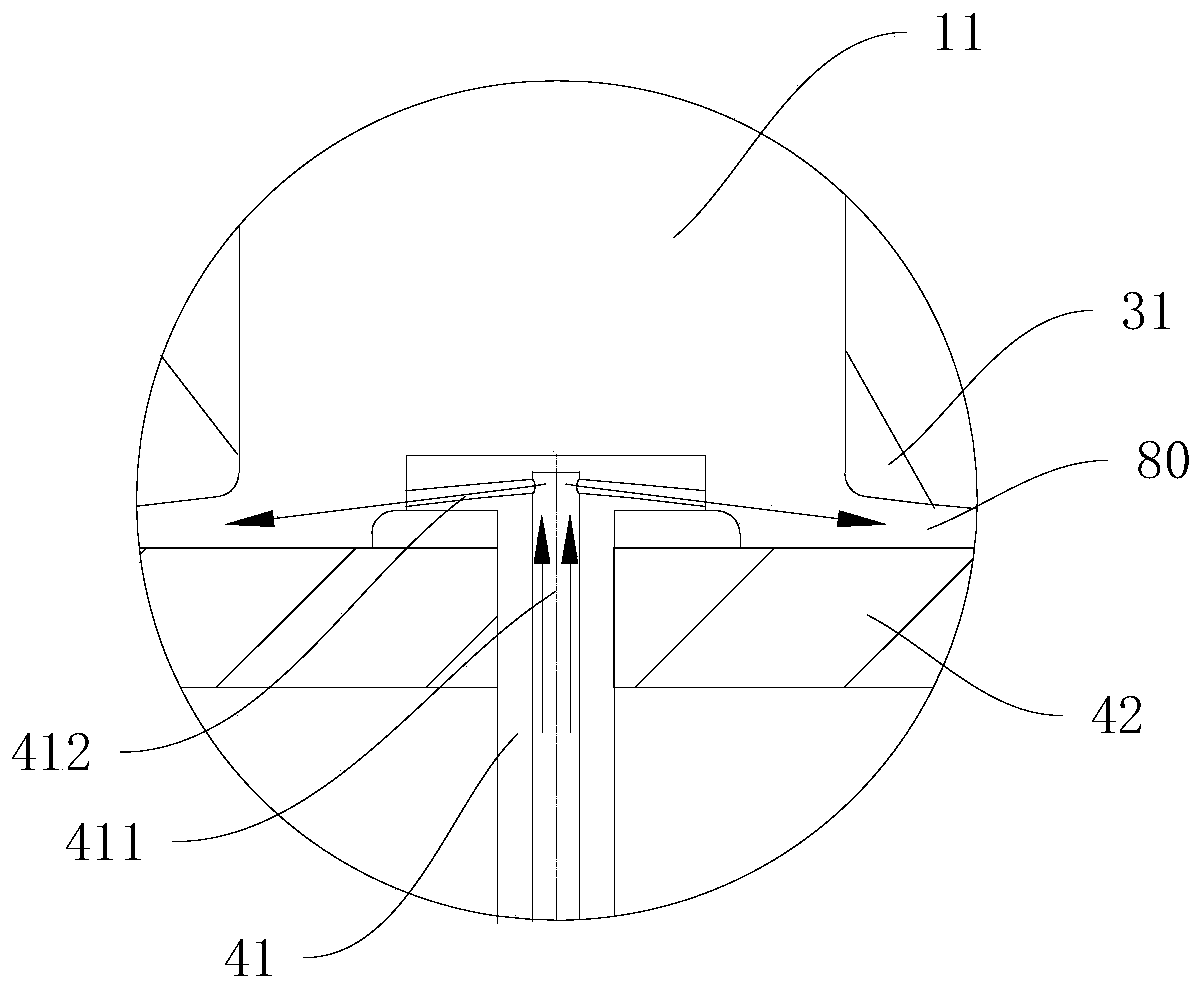
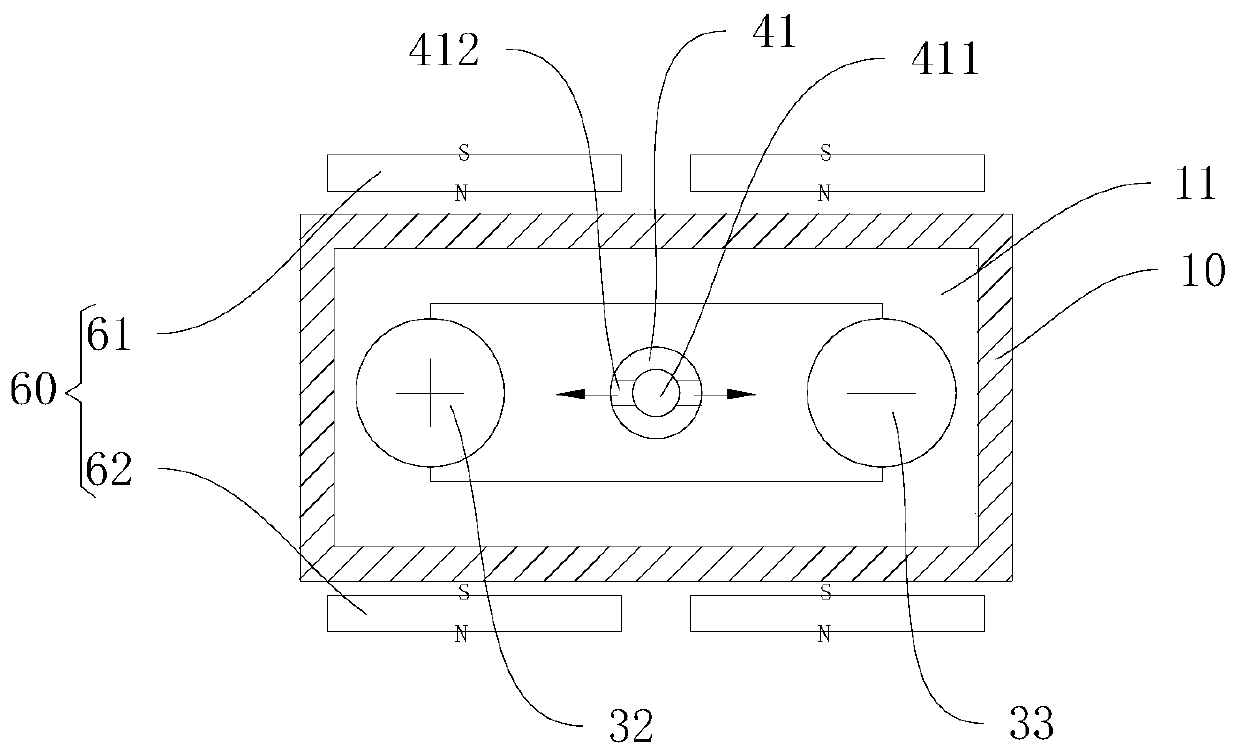
[0029] Such as Figure 1-Figure 4 As shown, the first frame body 10 is provided with a first airtight cavity 11 to prevent the first frame body 10 from communicating with outside air. Wherein, the first frame main body 10 is arranged in a cube, which has a simple structure and is easy to manufacture. Further, the first airtight cavity 11 is filled with stable gas such as helium, hydrogen or nitrogen, and t...


PUM


Abstract

Disclosed is a relay. The relay comprises a first frame body, a second frame body, a lead out terminal assembly, a pushing assembly, and a resetting assembly. A first closed chamber is disposed within the first frame body. A second closed chamber is disposed within the second frame body. The lead out terminal assembly comprises two stationary contacts disposed in the first closed chamber. The pushing assembly comprises a hollow pushing rod, a movable contact plate, and a movable iron core. The movable contact plate is fixed on one end of the hollow pushing rod, and is located within the first closed chamber, and a gap is formed between the movable contact plate and the stationary contacts. The movable iron core is disposed on the other end of the hollow pushing rod, and is located within the second closed chamber. The hollow pushing rod is provided with a gas vent conduit for connecting the first closed chamber and the second closed chamber and a nozzle in communication with the gas vent conduit, the nozzle being located above the movable contact plate. The relay has a better arc-extinguishing effect and control of a controlled circuit is more sensitive.

Description

technical field [0001] The invention relates to the field of electrical control devices, in particular to a relay. Background technique [0002] The relay is an electrical control device, usually used in automatic control circuits, it is an "automatic switch" that uses a small current to control the operation of a large current, and plays the role of automatic adjustment, safety protection and conversion circuit in the circuit. The existing relay usually includes a frame main body, a lead-out part, a moving spring part, a magnetic circuit system and a pushing mechanism. The lead-out part includes a lead-out and a static contact fixed at the bottom of the lead-out. The movable spring part is arranged in the frame main body, and a movable contact is arranged on it. The magnetic circuit system is used to control the pushing mechanism to push the moving spring part to work, so that the moving contact on the moving spring part is in contact with or separated from the static con...

Claims


Application Information

Patent Timeline
Patent Type & Authority Patents(China)
IPC IPC(8): H01H9/30H01H50/12H01H50/64
CPCH01H9/30H01H50/12H01H50/641H01H50/64
Inventor 陆涛姚保同冯俊汪鲁建
Owner BYD CO LTD
Why Eureka
Try Eureka