
A Modified Cylindrical/Spherical Lunberg Lens Antenna Based on Phased Array Feed

A Lumberg lens antenna and Lumberg lens technology are applied in wireless communication technology and radar fields, which can solve the problems of limited common effective omnidirectional radiation power and sensitivity of feed out of focus.

Active Publication Date: 2021-07-06
UNIV OF ELECTRONICS SCI & TECH OF CHINA
View PDF5 Cites 0 Cited by
  • Summary
  • Abstract
  • Description
  • Claims
  • Application Information

AI Technical Summary

Problems solved by technology

The problems existing in this feeding mechanism are: since only one feed source is working for one beam pointing, the total effective isotropic radiated power (EIRP) is limited; the scanning accuracy is directly determined by the number of feed sources, and there is a beam coverage blind area; The feed source is sensitive to out-of-focus, etc. Therefore, proposing a new feed source mechanism is of great significance to the practical application of the Lunberg lens

Method used


Image

  • A Modified Cylindrical/Spherical Lunberg Lens Antenna Based on Phased Array Feed
  • A Modified Cylindrical/Spherical Lunberg Lens Antenna Based on Phased Array Feed
  • A Modified Cylindrical/Spherical Lunberg Lens Antenna Based on Phased Array Feed

Examples


Embodiment Construction

[0020] The technical solutions of the present invention will be described in detail below in conjunction with the drawings and embodiments, but the protection scope of the present invention is not limited to the embodiments.

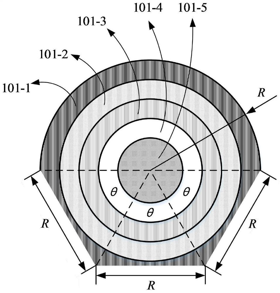
[0021] figure 1 It is a schematic diagram of a modified cylindrical Lunberg lens antenna according to the embodiment of the present invention. On the basis of the traditional cylindrical Lunberg lens, according to the diagram, one side surface is changed into three contiguous cut surfaces. Compared with the traditional cylindrical Lunberg lens, its area, volume and quality are all reduced by 8.6%. In this embodiment, the lens radius R=120 mm, θ=60°, and the corresponding dielectric constants of 101-1 to 101-5 are 1.2, 1.4, 1.6, 1.8, and 2, respectively.

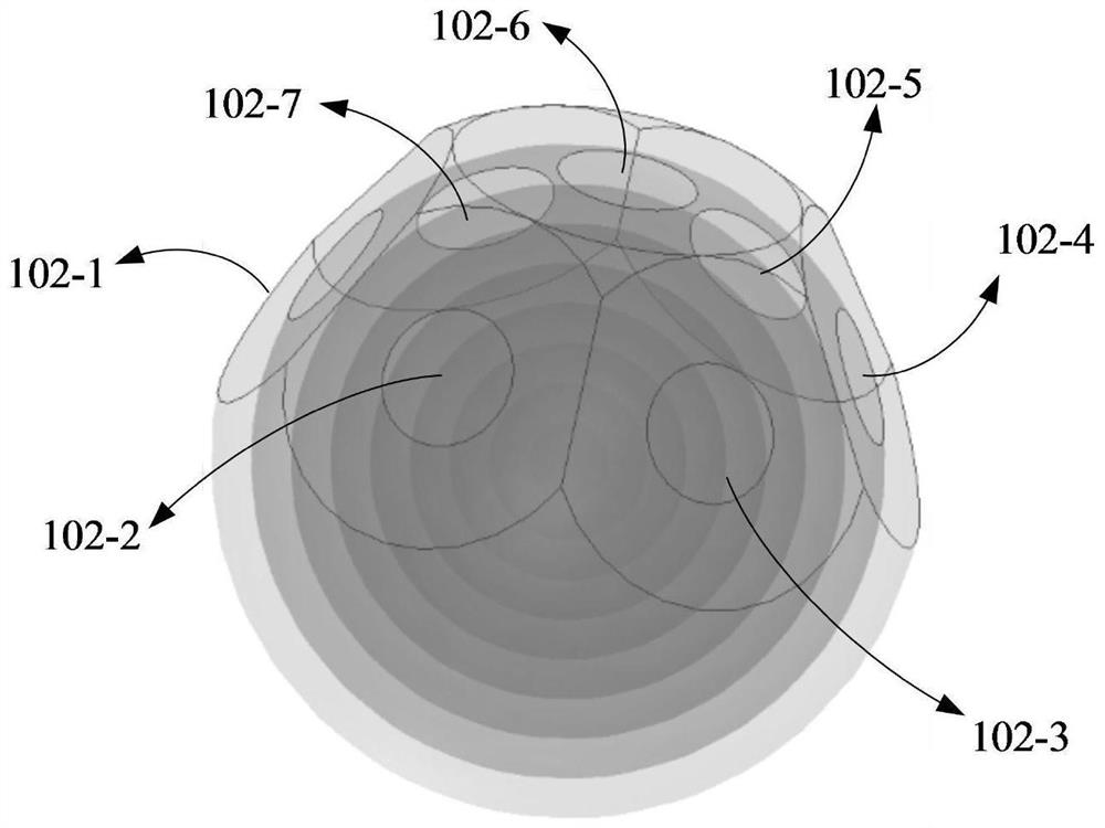
[0022] figure 2 It is a schematic diagram of a modified spherical Luneberg lens antenna according to the embodiment of the present invention. It is made by cutting off seven rounded corners by using ...


PUM


Abstract

The invention discloses a modified cylindrical / spherical Luneberg lens antenna based on phased array feeding, which belongs to the fields of wireless communication technology and radar technology. The antenna includes a modified cylindrical / spherical Lunberg lens, and several groups of active planar phased array antennas as feed sources. By rationally designing the positional relationship between the modified Lunberg lens and the phased array antenna, and optimizing the excitation coefficient of the phased array antenna as the feed source, the beam can be formed in the required direction, and the beam can be electronically scanned or simultaneously Multiple beams. Compared with the traditional Luneberg lens, the present invention has the characteristics and advantages of high gain, high effective isotropic radiated power (EIRP), high scanning accuracy, low mass, small volume, and adopts planar array feed source, which is convenient for processing and system integration. , can be used in radar and communication systems.

Description

technical field [0001] The invention belongs to the field of wireless communication technology and radar technology, and in particular relates to a modified cylindrical / spherical Luneberg lens antenna using a phased array for feeding. Background technique [0002] Multi-beam antenna (Multi-Beam Antenna) is one of the important forms of many antennas. Because of its advantages of high gain, low cost, and simultaneous multi-beam generation, it has been widely used in satellite communications, radar systems, and electronic countermeasures. a technical field. Common multi-beam antennas mainly fall into three categories: multi-beam phased array antennas, multi-beam reflector antennas, and multi-beam lens antennas. The traditional multi-beam antenna mostly adopts the form of phased array, the performance of the antenna is relatively stable, and the beam scanning control is very convenient, but the traditional phased array antenna needs a relatively large and complex feeding netwo...

Claims


Application Information

Patent Timeline
Patent Type & Authority Patents(China)
IPC IPC(8): H01Q15/08H01Q19/06H01Q21/00H01Q21/29
CPCH01Q15/08H01Q19/06H01Q21/0006H01Q21/29G01S13/42
Inventor 屈世伟冯鹏雨
Owner UNIV OF ELECTRONICS SCI & TECH OF CHINA
Learn More