
Clock synchronization method of wire switching type Ethernet

A clock synchronization and Ethernet technology, applied in time division multiplexing systems, electrical components, multiplexing communication, etc., can solve the problems of large effective communication bandwidth, increased system cost, and high complexity of synchronization methods

Inactive Publication Date: 2018-11-13
CHINESE AERONAUTICAL RADIO ELECTRONICS RES INST
View PDF2 Cites 2 Cited by
  • Summary
  • Abstract
  • Description
  • Claims
  • Application Information

AI Technical Summary

Problems solved by technology

The protocol uses a complex synchronization state machine, which requires a dedicated network offline configuration tool to calculate a large number of time configuration parameters for clock synchronization. At the same time, the synchronization process needs to be controlled by the state machine to realize two loopback communications during the cold start process and complete the solidification calculation. , Compression calculation, generally speaking, the complexity of this synchronization method is too high, it is not suitable for the clock synchronization design of high reliability and low complexity time-triggered network; IEEE1588 clock synchronization protocol is used as a clock for distributed measurement and control systems The synchronization protocol has been introduced into the switched Ethernet system to provide high-precision clock synchronization. This synchronization mechanism requires dedicated hardware support and increases the system cost. At the same time, this mechanism needs to be performed between master and slave clock devices to complete a synchronization. Four synchronous information frame transmissions occupy a large effective communication bandwidth

Method used


Image

  • Clock synchronization method of wire switching type Ethernet
  • Clock synchronization method of wire switching type Ethernet

Examples


Embodiment Construction

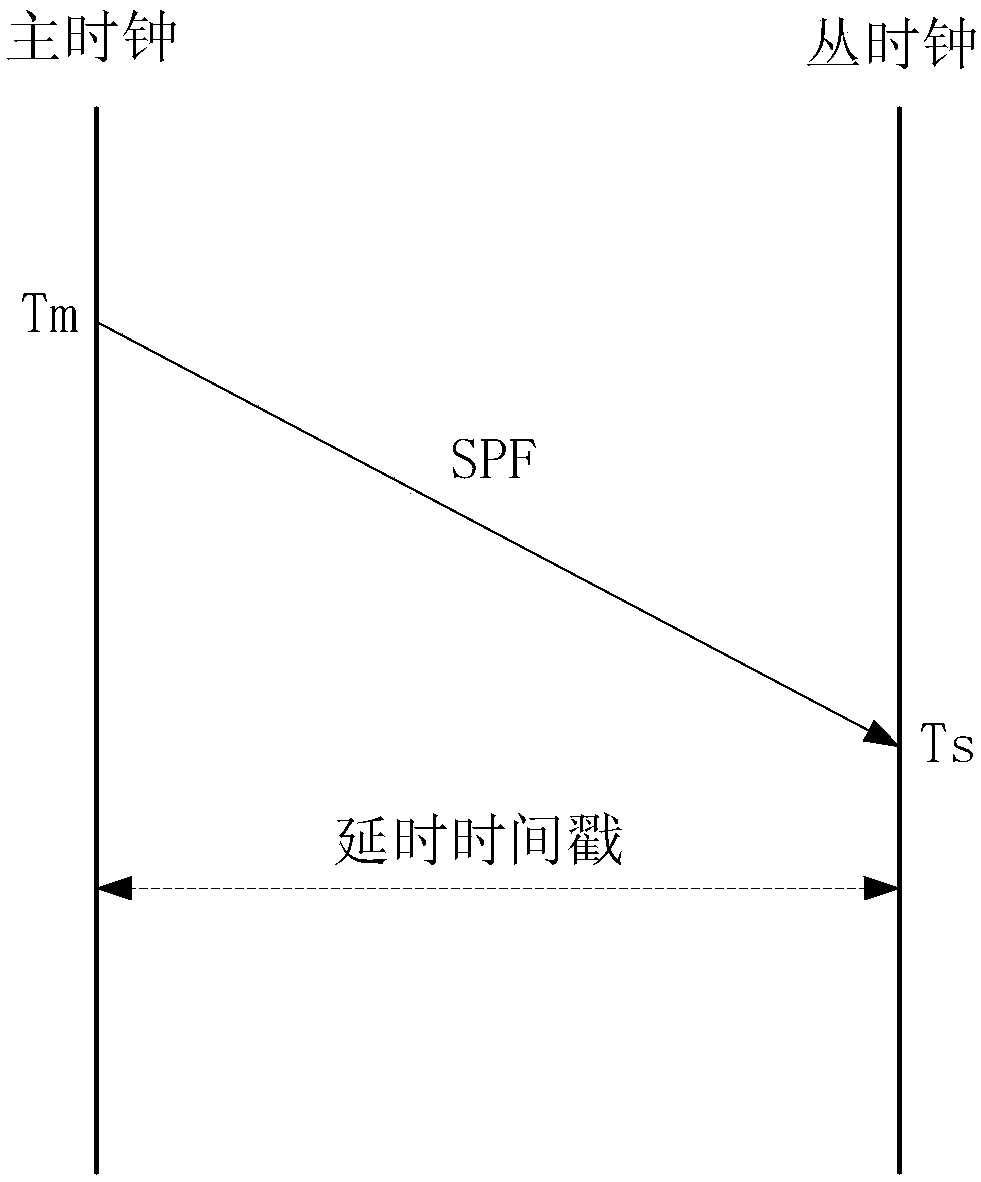
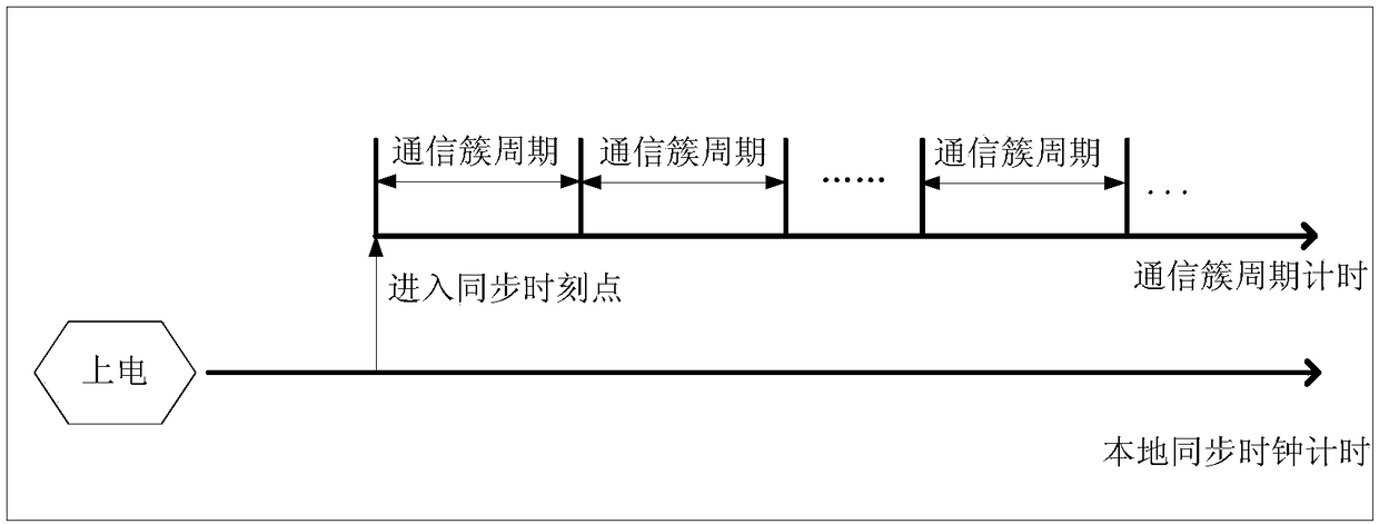
[0019] The present invention provides a clock synchronization method for wired switched Ethernet. The wired switched Ethernet uses a synchronization protocol frame for transmission, and the synchronization protocol frame carries the sending time stamp and high-precision time delay information of the master clock. The clock device transmits the synchronization protocol frame to the slave clock device, and transmits the time information of the master clock and the delay information of the transmission link to the slave clock device, so as to realize the function of correcting the deviation between the master and slave clocks and achieving the synchronization of the master and slave clocks. Ethernet data transmission provides a time-triggered global clock reference.

[0020] Several core time parameters involved in this technology: 1. Tm is the timing point of the local clock of SPF sent by the master clock; 2. Ts is the timing point of receiving the first bit of SPF from the cloc...


PUM


Abstract

The invention relates to a clock synchronization method of wire switching type Ethernet. A design concept based on simple synchronization protocol frame transmission is adopted, thereby providing clock synchronization with higher precision for the switching type Ethernet. The method enriches the clock synchronization design model selection method for the onboard bus of an aviation electronic system by the user, the method guarantees the high-precision demand of the clock synchronization, reduces the occupancy on the communication bandwidth by the clock synchronization information, and providesa global clock for the time triggering communication of the switching type Ethernet; and meanwhile, the application of the patent is independent of a hardware platform, wide in applicable range, andhas obvious market prospect and economic benefit.

Description

technical field [0001] The invention belongs to the technical field of clock synchronization of an airborne bus in an avionics system, in particular to a design method for clock synchronization of a switched network based on wired transmission under a time-triggered communication architecture. Background technique [0002] As the amount of airborne information and the degree of integration continue to increase, the requirements for safety-critical and mission-critical distributed communication applications continue to increase, which greatly promotes the development of aviation airborne network technology. [0003] Due to its own openness, traditional Ethernet cannot guarantee strict time characteristics, and cannot meet the high real-time requirements of current aviation airborne networks. As a deterministic aircraft data network bus, AFDX introduces a flow control mechanism based on Ethernet, and improves the determinism and real-time performance of Ethernet through virtua...

Claims


Application Information

Patent Timeline
IPC IPC(8): H04J3/06
Inventor 罗泽雄
Owner CHINESE AERONAUTICAL RADIO ELECTRONICS RES INST
Learn More