
Method for treating tail gas produced by thermal desorption of contaminated soil through pulse heating

A technology of pulse heating and soil heating, applied in the field of contaminated soil remediation, can solve the problems of not fundamentally decomposing pollutants, the need for activated carbon to be reprocessed, and increasing the processing cost, to achieve the effect of reducing energy consumption, saving costs and long life.

Inactive Publication Date: 2018-11-16
JINGMEN TUODA TECH CO LTD
View PDF2 Cites 3 Cited by
  • Summary
  • Abstract
  • Description
  • Claims
  • Application Information

AI Technical Summary

Problems solved by technology

Traditional thermal desorption is suitable for the treatment of volatile or semi-volatile organic compounds. It has the characteristics of high treatment efficiency, no secondary pollution, and usable soil after remediation. However, it also has high energy consumption and low heat utilization rate. Activated carbon needs to be processed again, etc.
Generally, the thermal desorption process is divided into two parts: thermal desorption and tail gas treatment. First, the pollutants are separated from the soil at a relatively high temperature. Second, the desorbed pollutants are treated by high-temperature incineration or activated carbon adsorption. High-temperature incineration usually requires It is carried out at a high temperature of 1200 °C, and the energy consumption accounts for more than 60% of the total energy consumption of the process. The high energy consumption limits the practical application of this technology; at the same time, the use of activated carbon to adsorb pollutants in the tail gas does not fundamentally decompose Pollutants, when the activated carbon is saturated, it needs to be treated again, which also increases the treatment cost

Method used


Image

  • Method for treating tail gas produced by thermal desorption of contaminated soil through pulse heating
  • Method for treating tail gas produced by thermal desorption of contaminated soil through pulse heating

Examples


Embodiment Construction

[0028] Embodiments of the present invention are described in detail below, examples of which are shown in the drawings, wherein the same or similar reference numerals denote the same or similar modules or modules having the same or similar functions throughout. The embodiments described below by referring to the figures are exemplary only for explaining the present invention and should not be construed as limiting the present invention.

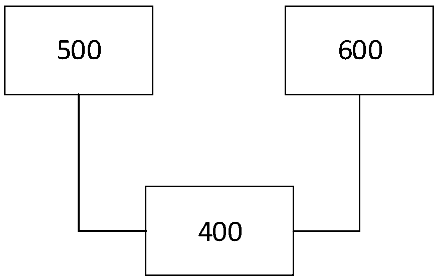
[0029] refer to figure 1 , according to an embodiment of the present invention, the method includes a dedusting treatment reactor 100 , a pulse heating catalytic degradation reactor 200 and an absorption treatment reactor 300 . According to an embodiment of the present invention, the dust removal treatment reactor 100 is used to remove particulate matter in the tail gas, the pulse heating type catalytic degradation reactor 200 is connected with the dust removal treatment reactor 100, and is used to purify the tail gas, and the absorption trea...


PUM


Abstract

The invention discloses a method for treating tail gas produced by thermal desorption of contaminated soil through pulse heating. The method comprises steps as follows: dust removal treatment, coolingtreatment, pulse heating type catalytic degradation and absorption treatment, wherein pulse heating type catalytic degradation is implemented as follows: the tail gas subjected to cooling and dust removal is sent into a catalysis treatment chamber for treatment, intermittent reactions of two stages of adsorption and heating are accompanied in the treatment process, and the adsorption process is implemented as follows: firstly, pollutants are adsorbed on a catalyst at the low temperature, a catalyst is heated to 150-500 DEG C after adsorption saturation is met through detection, and catalyticdegradation time is 2 seconds or longer; all the adsorbed pollutants are completely decomposed, a catalyst is regenerated in situ, and the regenerated catalyst can be continuously used for the next pulse adsorption stage.

Description

technical field [0001] The invention relates to the technical field of contaminated soil remediation, in particular to a pulse heating method for treating thermal analysis tail gas of polluted soil. Background technique [0002] The invention relates to a pulse heating method for thermal analysis tail gas of polluted soil. The method is developed on the basis of traditional thermal analysis technology, which is optimized and improved and combined with catalytic combustion technology. Traditional thermal desorption is suitable for the treatment of volatile or semi-volatile organic compounds. It has the characteristics of high treatment efficiency, no secondary pollution, and usable soil after remediation. However, it also has high energy consumption and low heat utilization rate. Activated carbon needs to be dealt with again and so on. Generally, the thermal desorption process is divided into two parts: thermal desorption and tail gas treatment. First, the pollutants are sep...

Claims


Application Information

Patent Timeline
IPC IPC(8): B01D53/02B01D53/14B01D53/18B01D53/86B09C1/06
CPCB01D53/02B01D53/14B01D53/1456B01D53/1481B01D53/18B01D53/86B01D53/8687B01D2255/2045B01D2255/2065B01D2255/20707B01D2255/20715B01D2255/2073B01D2255/20738B01D2255/20746B01D2255/20753B01D2255/20761B01D2255/2092B09C1/065
Inventor 郭利民刘银松
Owner JINGMEN TUODA TECH CO LTD
Learn More