
Metal coiled material machining system and method

A processing system and technology for metal coils, applied in other household appliances, household appliances, applications, etc., can solve the problems of low precision of the width of the coiled end and large fluctuation of the end face.

Active Publication Date: 2018-11-16
成都浩益科技有限公司
View PDF6 Cites 2 Cited by
  • Summary
  • Abstract
  • Description
  • Claims
  • Application Information

AI Technical Summary

Problems solved by technology

[0003] In order to solve the problems of low width precision of the coiled end of the existing coiled parts, large fluctuations in the end surface, and only large-scale coiled products can be prepared, the present invention provides a metal coil processing system and processing method

Method used


Image

  • Metal coiled material machining system and method
  • Metal coiled material machining system and method
  • Metal coiled material machining system and method

Examples


Embodiment 1

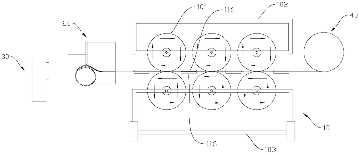
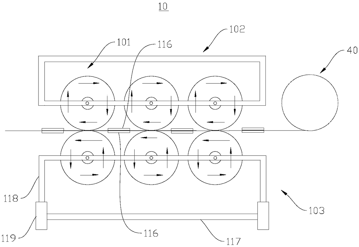
[0039] Please refer to figure 1 The metal coil processing system shown in the embodiment of the present invention includes: a shape correcting feeding device 10 , a forming device 20 and a cutting machine 30 . According to the production steps of shape correction, forming and material cutting, a shape correction feeding device 10, a forming device 20 and a material cutting machine 30 are arranged in sequence. Specifically, the feeding side of the shape-correcting feeding device 10 is set correspondingly to the coil material to be formed, and the discharging side of the shape-correcting feeding device 10 is set correspondingly to the feeding side of the forming device 20, so that the blank 40 after the shape-correcting is transported to Forming in the forming device 20. A material cutter 30 is provided on the discharge side of the molding device 20 . The cutting machine 30 of the present invention is preferably a laser cutting machine. Of course, other types of metal cutting...

Embodiment 2

[0054] This embodiment is basically the same as Embodiment 1, except that the shape of the third module 203 in this embodiment changes. Please refer to Figure 8, the sliding contact surface between the first module 201 and the third module 203 is a slope. The third module 203 slides obliquely upwards or downwards along the outer sidewall of the first module 201 while adjusting its position in the horizontal and vertical directions. The third module 203 includes a sliding surface 216 in contact with the first module 201 and a positioning surface 217 connected with the sliding surface 216 and located below the third module 203 . The positioning surface 217 corresponds to the forming channel 204 . A point on the positioning surface 217 is taken as the positioning point to realize three-point positioning, and the coil forming principle is the same as that in Embodiment 1. A slide rail 218 is provided on the slide surface 216 , and a third slide groove 219 matching with the sli...


PUM

PropertyMeasurementUnit
Lengthaaaaaaaaaa

Abstract

The invention discloses a metal coiled material machining system and method, and belongs to the field of material forming and machining. The metal coiled material machining system comprises a shape correcting and feeding device, a forming device and a material cutting machine. The feeding side of the shape correcting and feeding device corresponds to a to-be-formed coiled material, the dischargingside of the shape correcting and feeding device corresponds to the feeding side of the forming device, accordingly, blanks obtained after shape correcting are conveyed into the forming device to be formed, and the discharging side of the forming device is provided with the material cutting machine. By means of the metal coiled material machining system and method, automatic, stable and continuousproduction of coiled material products can be achieved, the product quality is reliable, and high size precision and product size adjusting sensitivity and flexibility are achieved.

Description

technical field [0001] The invention relates to the technical field of material forming and processing, in particular to a metal coil processing system and processing method. Background technique [0002] At present, metal coil products are generally pressed by upper and lower molds in a single piece, the production efficiency is low, continuous automatic production cannot be realized, and there is certain damage to the blank, so the quality cannot be guaranteed. Alternatively, the upper and lower rollers are used for continuous pressing, but the roller (roller) form cannot solve the problem of straight edges at both ends of the rolled part. In addition, coil products of different sizes require different molds for production, and the cost of tooling is extremely high. Moreover, the surface of the existing rolled parts is flat, but the width precision of the rolled end is low, the end surface fluctuates greatly, is flush, and has certain straight edges at both ends of the sl...

Claims


Application Information

Patent Timeline
IPC IPC(8): B21D21/00B21D51/10
CPCB21D21/00B21D51/10
Inventor 董立新罗征志孔卫东
Owner 成都浩益科技有限公司
Learn More