[0053] The present invention will be described in further detail below in conjunction with the accompanying drawings:
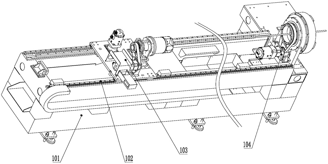
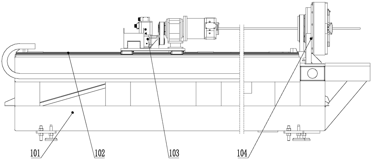
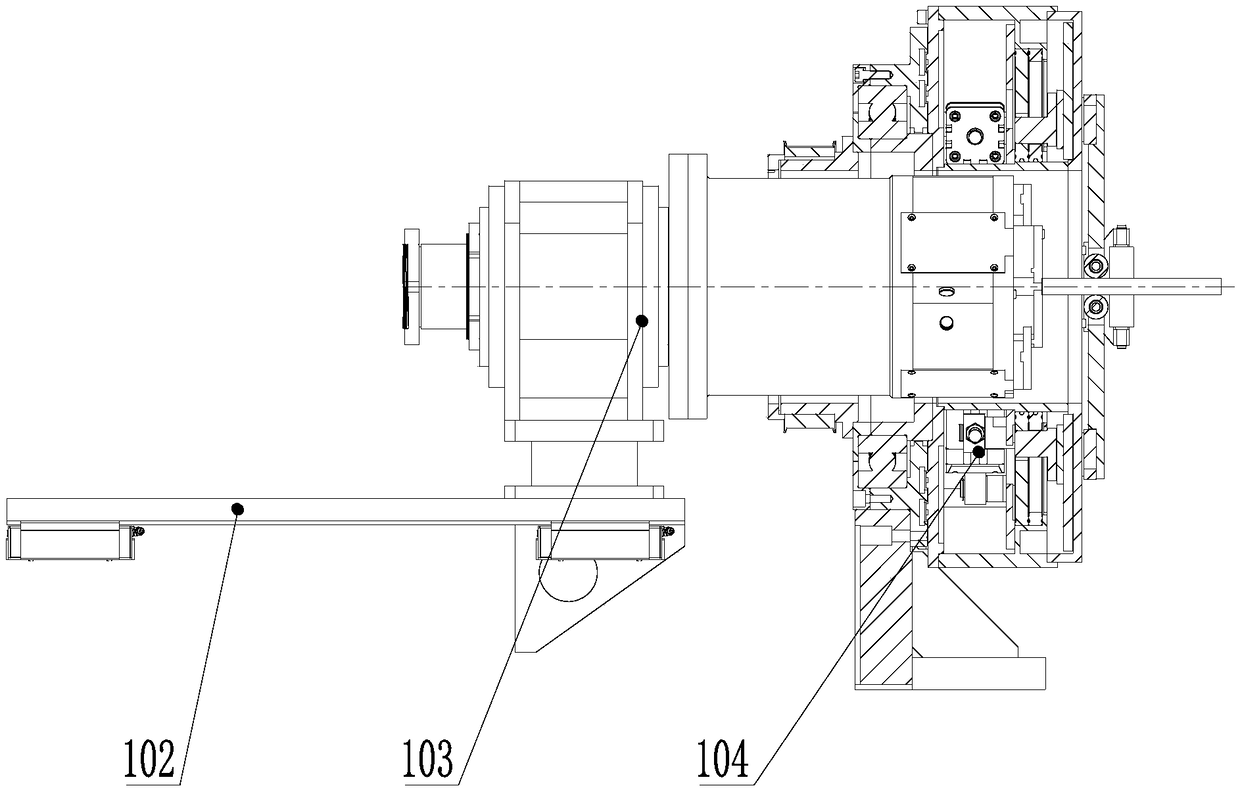
[0054] Such as Figure 1-3 As shown, a cutting machine for saving tails includes a frame 101, a first guide rail 102, a front chuck 104, and a rear chuck 103. The top surface of the frame 101 is provided with a first guide rail 102. A rear chuck 103 is provided on the first guide rail 102, and the rear chuck 103 can reciprocate along the direction of the first guide rail 102. The rack 101 at the end of the first guide rail 102 is provided with a front chuck 104. The chuck 104 and the rear chuck 103 are independently driven and have the same speed. The centers of the front chuck 104 and the rear chuck 103 are on the same axis. The front chuck 104 is provided with a side facing the rear chuck 103 A through hole extending to the inner side of the front chuck 104, and the rear chuck 103 can extend into the through hole of the front chuck 104. The front chuck 104 is provided with a through hole that allows the rear chuck 103 to extend into the interior, which can reduce the distance between the clamping portion of the rear chuck 103 and the clamping portion of the front chuck 104, thereby reducing the tail The length of the material increases the utilization rate of the material.
[0055] The rear chuck 103 is a conventional chuck. The rear chuck 103 adopts a conventional chuck, which is convenient to obtain materials, saves production costs, and can realize improvements to conventional machine tools.
[0056] Such as Figure 4 As shown, the front chuck 104 includes a fixed seat 11, a bearing seat 12 is provided on the top of the fixed seat 11, a bearing is provided on the bearing seat 12, and the outer ring of the bearing is fixed on the bearing seat 12. The inner ring is provided with a transmission sleeve 13, and one end of the transmission sleeve 13 is provided with a pneumatic clamping chuck 14. Specifically, the transmission sleeve 13 is provided with a flange, and the starting clamping chuck is fixed on the flange. The other end of the sleeve 13 is provided with a driven wheel 15, and the driven wheel 15 is sleeved on the transmission sleeve 13, a side wall of the fixing seat 11 facing the driven wheel 15 is provided with a motor seat 18, and the motor seat 18 is provided with The power device 19 is provided with a driving wheel 17 on the output shaft of the power device 19, and a transmission belt 16 is wound around the driving wheel 17 and the driven wheel 15. In this application, the power unit 19 adopts a motor reducer, the output shaft of the reducer is fixed with a driving wheel 17 and a transmission sleeve 13 is arranged on the bearing. The inner diameter of the transmission sleeve 13 is larger than the maximum outer diameter of the rear chuck 103, so that the rear The chuck 103 extends into the front chuck 104 to reduce the distance between the clamping part of the rear chuck 103 and the clamping part of the front chuck 104. At the same time, the front chuck 104 is driven independently, which can improve the universality of the front chuck 104. Sex.
[0057] Such as Figure 5 As shown, a pneumatic clamping chuck 14 includes a connecting disc 1, a chuck outer sleeve 2, a chuck inner sleeve 4, a separating disc 3, a mounting disc 5, a clamping device 6, a guide device 7, a conversion device 8 and a drive In the device 9, one end of the chuck casing 2 is provided with a connecting plate 1, and the other end of the chuck casing 2 is provided with a mounting plate 5, and between the connecting plate 1 and the mounting plate 5 is also provided with a card The inner sleeve 4 of the chuck coaxially arranged on the outer sleeve 2 of the disc, the mounting disc 5 is provided with a guide device 7, and the side of the guide device 7 located outside the outer sleeve of the chuck 2 has a clamping device 6, the guide device 7 A conversion device 8 is provided on the side inside the chuck casing 2, a drive device 9 is provided between the conversion device 8 and the connecting disk 1, and a partition disk 3 is provided between the conversion device 8 and the drive device 9, The conversion device 8 is driven by a driving device 9, and the conversion device 8 converts its axial rotation into a radial movement of the clamping device 6. Driven by the air cylinder 94, a certain elastic clamping force can be obtained, and the circular movement of the conversion device 8 is converted into the radial movement of the clamping device 6, thereby realizing the clamping of the material and improving the pneumatic clamping chuck 14 The continuity of movement improves the clamping effect.
[0058] Such as Figure 6-8 As shown, the chuck outer sleeve 2 includes an outer sleeve 21. The inner circumferential surface of the outer sleeve 21 is provided with a flange 22 protruding toward the center. The flange 22 is provided with a first mounting hole 23 and a second An arc-shaped hole 24, the first mounting hole 23 and the first arc-shaped hole 24 are spaced apart, and a first through hole 25 is provided in the center of the flange 22. The flange 22 is close to the end connected to the mounting plate 5. Providing a flange 22 inside the outer casing 21 can improve the rigidity and strength of the outer casing 21 and prolong its service life. The flange 22 is provided with a first arc-shaped hole 24 to reduce the weight of the outer casing 21 and make the outer casing 21 More portable.
[0059] Such as Picture 9 As shown, the partition plate 3 includes a partition plate body 31, a second through hole 33 is provided in the center of the partition plate body 31, and a second arc-shaped hole 32 is provided outside the second through hole 33. The two arc-shaped holes on the ground are evenly distributed on the outer circumference of the second through hole 33.
[0060] Such as Figure 21 As shown, the conversion device 8 includes a rotating disk and a guide disk. There are two rotating disks, a first rotating disk and a second rotating disk. The first rotating disk and the second rotating disk can rotate relatively. The first rotating disk is provided with a guide disk on one side of the first rotating disk, and the guide device 7 is connected to the rotating disk through the guide disk, and the rotating disk is connected to the driving device 9. The rotating disk drives the guide device 7 to move in the radial direction of the guide disk, and the circular movement of the rotating disk is converted into the radial movement of the clamping device 6 to realize the clamping of the workpiece.
[0061] Such as Figure 16-17 As shown, the rotating disk includes a rotating disk body 81. The center of the rotating disk body 81 is provided with a fourth through hole 83. The rotating disk body 81 is symmetrically provided with a third arc-shaped hole 82 and a second guide hole. 84. The third arc-shaped holes 82 and the second guide holes 84 are arranged alternately, and a second mounting hole 85 is provided on the inner side of the second guide hole 84. A second guide hole 84 is provided to guide the guide device 7 away from the center of the rotating disk body 81, so that the guide device 7 is farther and farther away from the center of the pneumatic clamping chuck 14.
[0062] The second guide hole 84 is an arc-shaped hole that gradually spirals from the inside to the outside. Setting the second guide hole 84 into an arc-shaped hole and spirally arranged from the inside to the outside can reduce the resistance generated when the guide device 7 is guided, which is beneficial to improve the flexibility of guiding the guide device 7 and reduce the guide device 7 and Wear between the rotating disks.
[0063] Such as Figure 18 As shown, the guide plate includes a guide plate body 86, a fifth through hole 88 is provided in the center of the guide plate body 86, and a third guide hole 87 is provided around the fifth through hole 88. The position of the guide hole 87 corresponds to the position of the guide device 7. The third guide hole 87 is used to guide the guide device 7. When the rotating disc guides the guide device 7 to the outside, the guide device 7 can be moved along the third guide hole 87 on the guide disc, even if the guide device 7 is pneumatically installed. The center of the chuck 14 moves radially outward.
[0064] Such as Figure 19-21 As shown, the driving device 9 includes a first driving device 919 and a second driving device 929, and the first driving device 919 and the second driving device 929 are arranged at 90°. A first driving device 919 and a second driving device 929 are provided to drive the horizontal clamping device 6 and the vertical clamping device 6 of the pneumatic clamping chuck 14 to realize the clamping of workpieces with irregular cross-sections. , Improve the versatility of the pneumatic clamping chuck 14.
[0065] There are two first driving devices 919 and two second driving devices 929. Two first driving device 919 and second driving device 929 are respectively provided, which can increase the driving force. At the same time, when one of the driving devices 9 fails, the other driving device 9 can continue to work without affecting the operation of the equipment. The use of the clamping chuck 14 adds double insurance.
[0066] Such as Figure 20-21 As shown, the first driving device 919 and the second driving device 929 each include an air cylinder 94, a first fixed shaft 93, and a second fixed shaft 95. The tail of the air cylinder 94 is connected to the first fixed shaft 93. The end of the push rod 94 is connected to the second fixed shaft 95, the first fixed shaft 93 is fixed on the chuck casing 2, and the second fixed shaft 95 is fixed on the rotating disk. The air cylinder 94 is used, the power source is clean, which can avoid pollution to the workpiece. At the same time, the gas has a certain degree of compressibility, can produce a certain buffer when clamping the workpiece, and play a certain protective effect on the workpiece.
[0067] Specifically, the first fixed shaft 93 of the first driving device 919 is fixed on the chuck casing 2, the second fixed shaft 95 of the first driving device 919 is fixed on the first rotating disk, and the cylinder body of the air cylinder 94 is fixed to the first fixed shaft. The shaft 93 is connected, the push rod of the air cylinder 94 is connected to the second fixed shaft 95, the first fixed shaft 93 of the second drive device 929 is also fixed on the chuck casing 2, and the second fixed shaft 95 of the first drive device 919 is fixed on On the second rotating disc, the cylinder body of the cylinder 94 is connected to the first fixed shaft 93, and the push rod of the cylinder 94 is connected to the second fixed shaft 95. Specifically, the first fixed shaft 93 is installed in the first installation of the chuck casing 2. In the hole 23, the second fixed shaft 95 is installed in the second mounting hole 85 of the rotating disk. In order to avoid interference between the second fixed shaft 95 and the partition plate 3, a second arc-shaped hole 32 is provided on the partition plate 3. The position of the shaped hole 32 corresponds to the position of the movement track of the second fixed shaft 95. When the air cylinder 94 of the first driving device 919 operates, the first rotating disk is rotated around the inner sleeve 4 of the chuck, clockwise or counterclockwise, When the first rotating disk rotates, the first guiding device 7 is driven to move. The first guiding device 7 moves along the radial direction of the pneumatic clamping chuck 14 to drive the first clamping device 6 to move, so that the pneumatic clamping chuck 14 moves in one direction. When the air cylinder 94 of the second driving device 929 moves, the second rotating disk rotates clockwise or counterclockwise when the cylinder 94 of the second driving device 929 moves. When the second rotating disk rotates, the second guiding device 7 is driven to move , The second guide device 7 moves along the radial direction of the pneumatic clamping chuck 14 to drive the second clamping device 6 to move to realize the clamping action of the pneumatic clamping chuck 14 in the other direction, that is, perpendicular to the first clamping Holding device 6 direction clamping action.
[0068] Such as Picture 12 As shown, the guiding device 7 includes a first guiding device 7 and a second guiding device 7. The first guiding device 7 and the second guiding device 7 are arranged at 90°. Specifically, the first guiding device 7 passes through The guide plate is connected to the first rotating plate, the second guide device 7 is connected to the second rotating plate through the guide plate, the first drive device 919 is connected to the first rotating plate, and the second drive device 929 is connected to the The second rotating disc is connected. The first guiding device 7 and the second guiding device 7 are provided to respectively guide the horizontal clamping device 6 and the vertical clamping device 6 of the pneumatic clamping chuck 14 to realize the horizontal and vertical direction. To clamp, improve the clamping degree of the workpiece.
[0069] The first guide device 7 and the second guide device 7 both include a second guide rail 71, a sliding block 72, a guide seat 73 and a cover 74, and the second guide rail 71 is provided with a sliding block 72 capable of sliding along it, The sliding block 72 is provided with a guide seat 73, two ends of the guide seat 73 are provided with a vertical plate 732 extending toward the second guide rail 71 side, and the end of the vertical plate 732 is provided with a baffle. A guide rail is arranged between the guide seat 73 and the mounting disk 5 to reduce the friction between the guide seat 73 and the mounting disk 5, so that the guide seat 73 runs more smoothly and improves the smoothness of the pneumatic clamping chuck 14 operation.
[0070] Such as Figure 14 As shown, the guide seat 73 includes a plate body 731, one side of the plate body 731 is provided with a guide column 733, and the other side of the plate body 731 is provided with a vertical plate 732, the vertical plates 732 are respectively arranged at Both ends of the side. The guide seat 73 is set to a Y-shape. Through the cooperation of the guide seat 73 and the baffle, the guide seat 73 is slidably installed on the mounting plate 5, which makes the structure more compact and reduces the difference between the clamping device 6 and the connecting plate 1. The length of the space effectively shortens the remaining length of the tailings and improves the utilization rate of the workpiece.
[0071] Such as Figure 12-13 As shown, the clamping device 6 includes a first clamping device 6 and a second clamping device 6, the first clamping device 6 and the second clamping device 6 are each provided with two, the first clamping device The holding device 6 and the second holding device 6 are arranged at 90°. The first clamping device 6 and the second clamping device 6 are provided to clamp the workpiece clamped by the pneumatic clamping chuck 14 from the horizontal direction and the vertical direction respectively, which can realize the clamping of workpieces with irregular cross-sections. The versatility of the pneumatic clamping chuck 14 is improved.
[0072] Such as Figure 13 As shown, the first clamping device 6 and the second clamping device 6 both include a claw 61, a pin 62 and a roller 63. One end of the claw 61 is fixed on the guide device 7, and the other end faces the chuck. The end of the claw 61 extending toward the center of the chuck is provided with a pin 62, and a roller 63 is sleeved on the pin 62. By setting the roller 63 to contact the workpiece, the movement of the rear chuck 103 during the clamping process can realize the axial movement of the workpiece in the clamping state, avoiding repeated clamping of the workpiece, and improving the cutting efficiency of the workpiece .
[0073] Such as Figure 10-11 As shown, the mounting disk 5 includes a mounting disk body 51, a circular platform 54 is provided in the center of one side of the mounting disk body 51, and a third through hole 55 is provided on the circular platform 54. The outer circumference of the circular platform 54 A boss 52 extending to the outer contour of the mounting plate 51 is provided on the surface. The other side of the mounting plate 51 is provided with a groove 56 corresponding to the boss 52. The top surface of the boss 52 is provided with a A guide hole 53, the first guide hole 53 penetrates from the top surface of the boss 52 to the bottom surface of the groove 56. A boss 52 is provided on one side of the mounting plate 5, and a groove 56 recessed into the boss 52 is provided on the other side of the boss 52 for installing the guide rail, the sliding block 72 and the guide seat 73, making full use of the mounting plate 5 The space on the thickness effectively reduces the thickness of the pneumatic clamping chuck 14, which is beneficial to reduce the length of the workpiece tail and improve the utilization rate of the workpiece.
[0074] Specifically, the second guide rail 71 of the guide device 7 is fixed in the groove 56 of the mounting plate 5, the slider 72 can reciprocate on the second guide rail 71, the guide seat 73 is fixed on the slider 72, and the guide seat 73 stands upright. The plate 732 extends through the first guide hole 53 on the mounting plate 5 to the other side of the mounting plate 5. The ends of the two vertical plates 732 are equipped with baffles, so that the guide device 7 can be mounted on the mounting plate 5. The radial reciprocating movement of the mounting plate 5, the guide post 733 of the guide seat 73 is located on the side of the mounting plate 5 facing the inner side of the chuck casing 2, and the baffle is located on the side of the mounting plate 5 facing the outer side of the chuck casing 2. Fixed on the baffle, as the guide device 7 moves, the guide post 733 of the guide device 7 rotates through the conversion device 8; wherein the guide post 733 of the first guide device 7 passes through the third guide hole 87 on the guide plate and is inserted into the In the second guide hole 84 on a rotating disc, the guide post 733 of the second guide device 7 passes through the third guide hole 87 on the guide disc and is inserted into the second guide hole 84 on the second tour disc. In this way, when When the first rotating disk rotates clockwise, the guide post 733 of the first guiding device 7 moves toward the center of the rotating disk under the guidance of the second guide hole 84 of the first rotating disk, and at the same time moves in the third guide hole of the guide disk. Under the guiding action of 87, it is ensured that the guide post 733 does not move axially, so that the distance between the two clamping devices 6 arranged oppositely is shortened, and the clamping of the workpiece is realized. On the contrary, when the first rotating disk rotates counterclockwise, the first guiding The guide column 733 of the device 7 moves away from the center of the rotating disk under the guidance of the second guide hole 84 of the first rotating disk, so that the distance between the two clamping devices 6 arranged oppositely is increased, and the workpiece is loosened. open. Similarly, the movement mode of the second guiding device 7 arranged perpendicular to the first guiding device 7 is the same as that of the first guiding device 7. When the second rotating disc rotates clockwise, the guide post 733 of the second guiding device 7 Under the guidance of the second guide hole 84 of the second rotating disk, it moves toward the center of the rotating disk. At the same time, under the guidance of the third guide hole 87 of the guide disk, it is ensured that the guide post 733 does not undergo axial displacement, so that the relatively disposed The distance between the two clamping devices 6 is shortened to realize the clamping of the workpiece. On the contrary, when the second rotating disk rotates counterclockwise, the guide post 733 of the second guiding device 7 guides the second guide hole 84 of the second rotating disk Under the action of moving away from the center of the rotating disk, the distance between the two oppositely arranged clamping devices 6 is increased, and the workpiece is released. In this way, the clamping device 6 is driven by the guide device 7 to realize the separation. Clamp the workpiece in two directions, and can realize unequal distance clamping according to the length of the workpiece in both directions, that is, the clamping distance in the direction of the first clamping device 6 can be the same as the direction of the second clamping device 6 The clamping distances are not equal.
[0075] After the pneumatic clamping chuck 14 is assembled, the inner sleeve 4 of the chuck sequentially passes through the second through hole 33 of the partition plate 3, the fourth through hole 83 of the rotating plate and the fifth through hole 88 of the guide plate. One end of 4 is connected to the third through hole 55 of the mounting plate 5, and the other end is connected to the connecting plate 1, so that after the pneumatic clamping chuck 14 is installed on the flange of the transmission sleeve 13, the rear chuck 103 can be penetrated into In the front chuck 104, the clamping part of the rear chuck 103 is made close to the clamping device 6 of the front chuck 104 to reduce the length of the tail material and increase the utilization rate of the workpiece.
[0076] The above technical solution is only one embodiment of the present invention. For those skilled in the art, on the basis of the application methods and principles disclosed in the present invention, it is easy to make various types of improvements or modifications, not limited to The method described in the above specific embodiments of the present invention, therefore, the method described above is only preferred, and does not have a restrictive meaning.