
Power supply device for electric spark machining

A power supply device and electric spark technology, applied in electric processing equipment, accessory devices, metal processing equipment, etc., can solve the problems of easy loss of bolts, cumbersome disassembly, and easy dislocation of power supply protection cover installation, so as to achieve easy disassembly and increase accuracy Effect

Active Publication Date: 2018-11-16
嘉兴笼列电子商务有限公司
View PDF8 Cites 0 Cited by
  • Summary
  • Abstract
  • Description
  • Claims
  • Application Information

AI Technical Summary

Problems solved by technology

[0004] In order to solve the above-mentioned problems, the present invention provides a power supply device for electric discharge machining, which can solve the problems of cumbersome disassembly of the power supply protection cover existing in the cleaning of the power supply protection cover of the electric discharge machine tool, easy loss of disassembled bolts, and inability to clean the power supply protection cover. It is easy to dislocation when installing the power supply protection cover; it can realize the removal and installation of the protection cover for the power supply of the EDM machine tool, and the function of firmly supporting the protection cover when cleaning. It will not be lost, the power supply cover can be fixed when it is cleaned, and the power supply cover will not be misplaced when it is installed, etc.

Method used


Image

  • Power supply device for electric spark machining
  • Power supply device for electric spark machining
  • Power supply device for electric spark machining

Examples


Embodiment Construction

[0026] In order to make the technical means, creative features, goals and effects achieved by the present invention easy to understand, the present invention will be further described below in conjunction with specific illustrations. It should be noted that, in the case of no conflict, the embodiments in the present application and the features in the embodiments can be combined with each other.

[0027] like Figure 9 As shown, the existing electric discharge machine tool pulse power supply protective cover is installed on the power supply of the electric discharge machine tool by bolts.

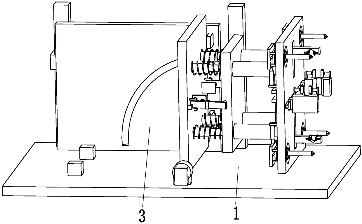
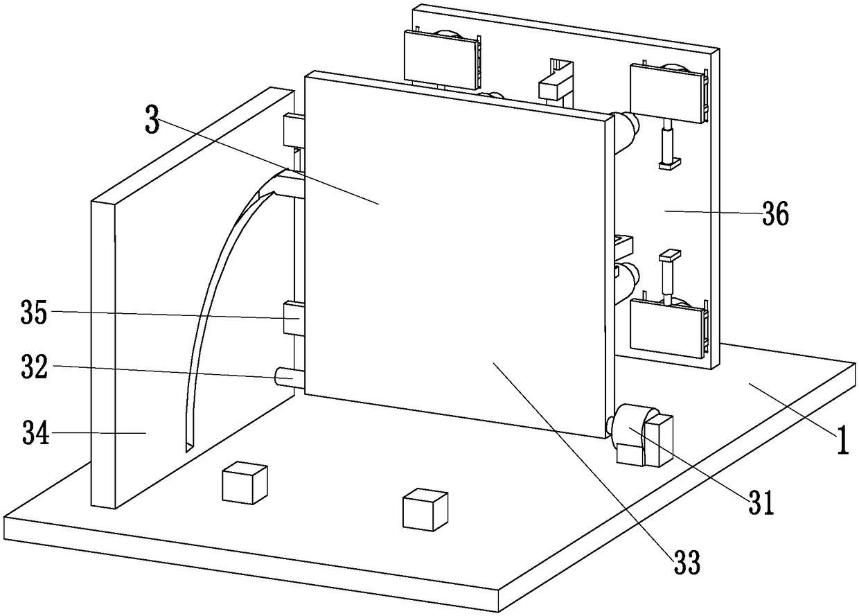
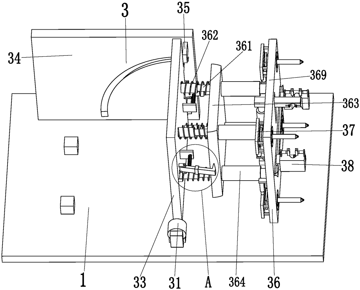
[0028] like Figure 1 to Figure 8 As shown, the power supply device for electric discharge machining includes a clamping base plate 1 and a dismounting device 3 , a rubber pad is arranged on the top left end of the clamping base plate 1 , and the dismounting device 3 is installed on the left end top of the clamping base plate 1 .

[0029] Described dismantling device 3 comprises dismantlin...


PUM


Abstract

The invention relates to a power supply device for electric spark machining. The power supply device comprises a clamping bottom plate and a demounting device. A rubber pad is arranged at the top of the left end of the clamping bottom plate. The demounting device is mounted at the top of the left end of the clamping bottom plate. The demounting device comprises a demounting motor, a demounting rotating shaft, a demounting rotating plate, a demounting vertical plate, a demounting limiting plate, a telescopic mechanism, four demounting mechanisms and fixing mechanisms. The telescopic mechanism comprises demounting telescopic rods, demounting springs, a demounting connecting plate, demounting pushing rods, a clamping hook, a clamping hook spring, a pushing push rod, a spring connecting plate,a demounting fixing plate and a clamping hook lug seat. According to the power supply device, the difficult problems that when a power supply protective cover of an existing electric spark machine tool is cleared, demounting of the power supply protective cover is tedious, demounted bolts are prone to being lost, and the power supply protective cover cannot be fixed when cleared and is prone to dislocation when mounted can be solved.

Description

technical field [0001] The invention relates to the technical field of electric discharge machine tool processing, in particular to a power supply device for electric discharge processing. Background technique [0002] EDM machine tool is a kind of machine tool equipment that uses the principle of electric spark discharge to erode metal surfaces to process metal parts; because the principle of EDM is different from that of ordinary metal cutting, EDM machine tools are similar to ordinary metal cutting machine tools. are different in structure. First of all, it has a high-energy pulse power supply device to provide energy for generating electric sparks. The main function is to generate repeated high-intensity electric pulses on tool electrodes and workpiece electrodes to generate discharge electric sparks; pulse control of EDM machine tools It is carried out by pulse power supply. The pulse power supply is installed on the outside of the EDM machine tool. When the pulse powe...

Claims


Application Information

Patent Timeline
Patent Type & Authority Applications(China)
IPC IPC(8): B23H1/02B23H11/00
CPCB23H1/02B23H11/00
Inventor 李鸿梁荣
Owner 嘉兴笼列电子商务有限公司
Learn More