
A wire electric discharge cutting device

A technology of cutting equipment and electric discharge wire, which is applied in the field of machine tools, can solve the problems of unfavorable metal wire movement and electrical conduction, and the increase of the thickness of the metal wire surface, so as to achieve the effect of keeping the surface of the machine body clean

Active Publication Date: 2019-10-01
ANHUI MINGGUANG RUISHENG MACHINERY
View PDF6 Cites 4 Cited by
  • Summary
  • Abstract
  • Description
  • Claims
  • Application Information

AI Technical Summary

Problems solved by technology

[0003] When using a wire electric discharge machine, the metal wire melts the workpiece, and some workpieces are absorbed on the surface of the wire after melting, resulting in an increase in the thickness of the surface of the wire, which is not conducive to the movement of the wire to conduct electricity; in view of this, the present invention provides a A wire electric discharge cutting device has the following characteristics:

Method used

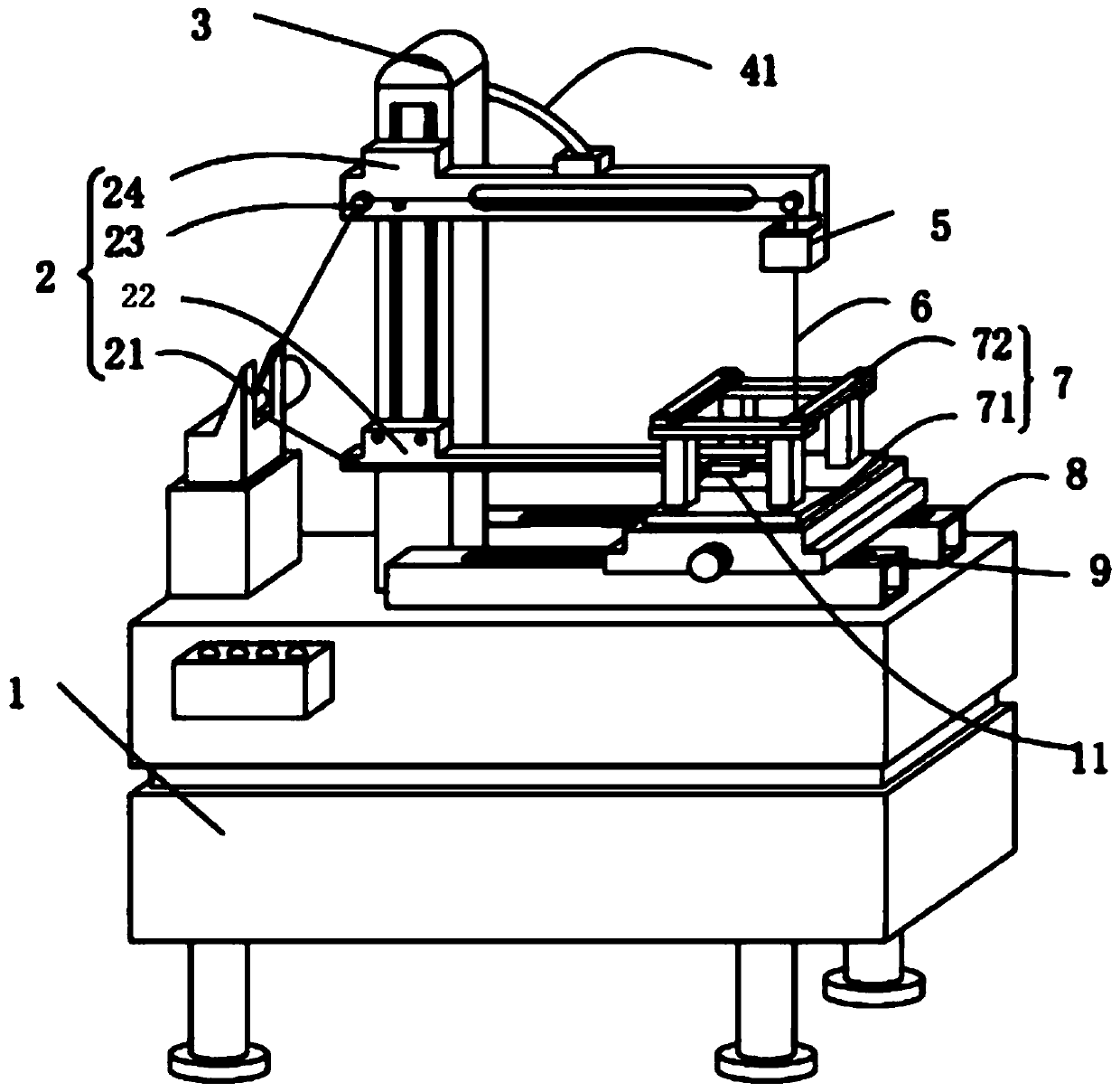
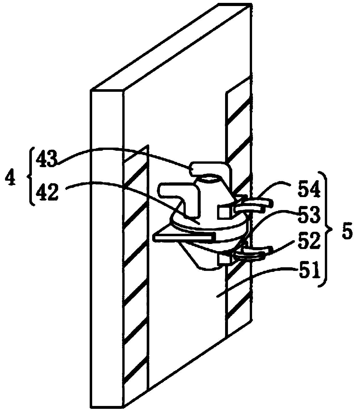
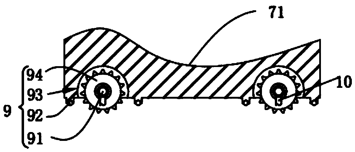

Image

  • A wire electric discharge cutting device
  • A wire electric discharge cutting device
  • A wire electric discharge cutting device

Examples


Embodiment Construction

[0027] In order to make the technical methods, creative features, goals and effects achieved by the present invention easy to understand, the present invention will be further described below in conjunction with specific embodiments.

[0028] Such as figure 1 As shown, a wire electric discharge cutting device according to the present invention includes a body 1, a wire routing mechanism 2, a support column 3, a water adding mechanism 4, a fixing mechanism 5, a metal wire 6, an installation mechanism 7, a support plate 8, an adjustment Mechanism 9, limiting mechanism 10 and cleaning mechanism 11; the support column 3 is installed in the center of the top surface of the body 1, and the wiring mechanism is installed on the side wall of the support column 3 and the top surface of the body 1 2, and the inside of the wire routing mechanism 2 is slidingly connected to the metal wire 6; one end of the wire routing mechanism 2 is installed with the fixing mechanism 5, and the inside of...


PUM


Abstract

The invention relates to the technical field of machine tools, in particular to a wire-cut electrical discharge machining device. The device comprises a machine body, a wire passing mechanism, a supporting column, a water feeding mechanism, a fixing mechanism, a metal wire, a mounting mechanism, supporting plates, an adjusting mechanism, a limiting mechanism and a cleaning mechanism, the metal wire rotates on the side wall of the wire passing mechanism, and the water feeding mechanism is installed at the bottom end of the wire passing mechanism. According to the device, when the metal is cut,the liquid in the water feeding mechanism converges into huge water flow and flows to the metal surface along with the metal wire, the melted metal is quickly washed away, attachments on the metal wire are reduced, the cleaning mechanism is installed at the bottom end of the wire passing mechanism, the metal wire moves up and down in a zigzag mode inside the cleaning mechanism, so that the surfaceof the metal wire is fully contacted with the interior of the cleaning mechanism to clean up metal attachments on the surface of the metal wire; the water feeding mechanism and the cleaning mechanismare located on the top end of the mounting mechanism, the liquid and the metal fragments directly fall on the v-shaped top surface of the mounting mechanism, so that the metal fragments can be conveniently washed away by the liquid.

Description

technical field [0001] The invention relates to the technical field of machine tools, in particular to a wire electric discharge cutting device. Background technique [0002] Electric spark wire cutting machine belongs to the category of electric processing. When the former Soviet Union Lazalianke and his wife studied the phenomenon and cause of the damage of switch contacts by spark discharge corrosion, they found that the instantaneous high temperature of electric spark can melt and oxidize local metal Corroded away, thus creating and inventing the electric discharge machining method. [0003] When using a wire electric discharge machine, the metal wire melts the workpiece, and some workpieces are absorbed on the surface of the wire after melting, resulting in an increase in the thickness of the surface of the wire, which is not conducive to the movement of the wire to conduct electricity; in view of this, the present invention provides a A wire electric discharge cutting...

Claims


Application Information

Patent Timeline
Patent Type & Authority Patents(China)
IPC IPC(8): B23H7/02B23H11/00
Inventor 臧晨晨
Owner ANHUI MINGGUANG RUISHENG MACHINERY
Learn More