Cloth unwinding device for textile
A technology of unwinding device and cloth, which is applied in the direction of winding strips, thin material handling, transportation and packaging, etc. It can solve the problems of affecting the quality of finished products, easy to get dust and dirt, and the cloth rolls are stretched out. Effects of Volume Jobs
- Summary
- Abstract
- Description
- Claims
- Application Information
AI Technical Summary
Problems solved by technology
Method used
Image

Examples
Embodiment 1
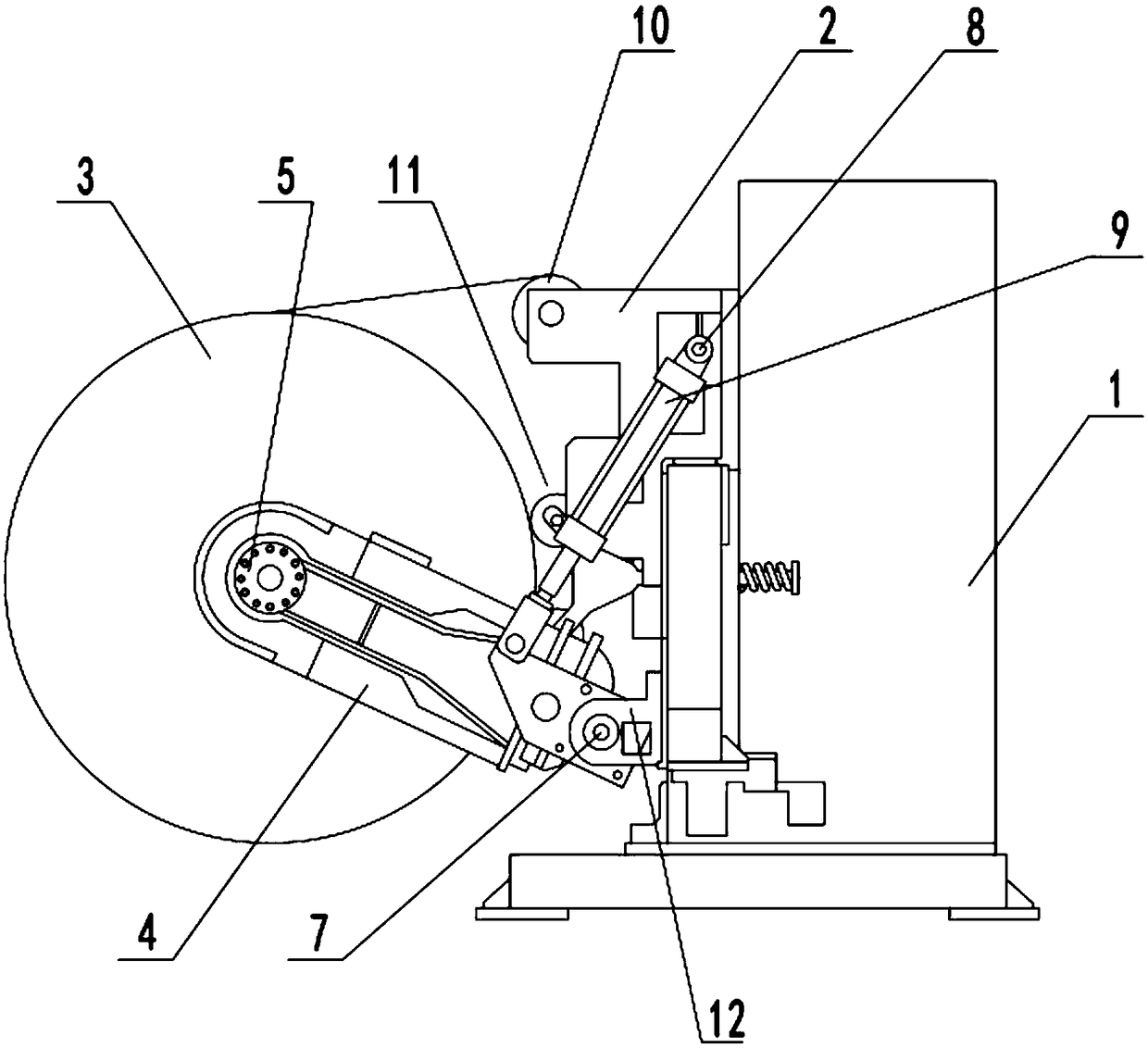
[0019] see Figure 1~2 , in an embodiment of the present invention, a fabric unwinding device for textiles, comprising an unwinding box 1, a fixed seat 2 and an unwinding seat 4, a fixed seat 2 is fixedly installed on one side of the unwinding box 1, and a fixed A pair of unwinding seats 4 is installed on the seat 2, and a drum 14 is installed between the two unwinding seats 4, and a motor 6 is installed on one of the unwinding seats 4 through a motor mounting plate 5, and the rotating drum 14 is installed by The motor 6 is driven to rotate, which can realize the unwinding operation of the cloth roll installed on the rotating drum 14, and the fixing seat 2 is also equipped with a pressing mechanism 11, which is used to contact with the cloth roll, so that the cloth can be kept tightly wound. To prevent the winding and dragging phenomenon caused by inertial movement when the motor 6 is stopped;
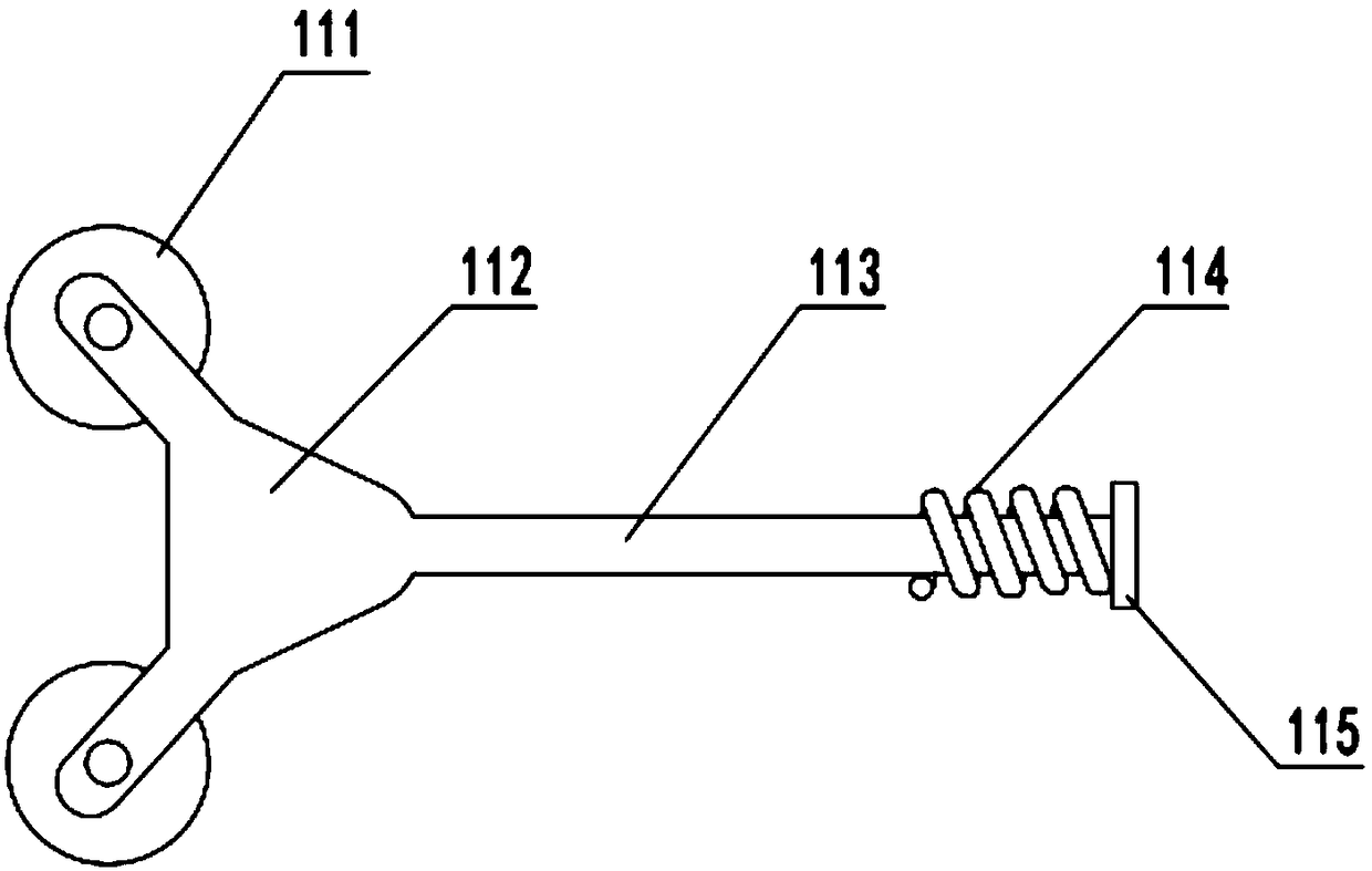
[0020] Specifically, the pressing mechanism 11 includes a pressing roller 111 and...
Embodiment 2
[0023] see Figure 1~3 , after the last roll of cloth unwinding is completed, the cloth needs to be replaced again. In this process, due to the narrow and small working space on site, it is not convenient to change the roll. Therefore, this embodiment improves the installation method of the unwinding seat 4. specific:
[0024] The ends of the two unwinding seats 4 are hingedly connected with the mounting lugs 12 fixed on the fixed seat 2 through the pin shaft 7, and the fixed seat 2 is also equipped with a cylinder 9 through a cylinder mounting seat 8, and the output of the cylinder 9 One end is hingedly connected with one of the unwinding seats 4, and when the roll needs to be changed, the cylinder 9 can be controlled to extend, so that the distance between the two unwinding seats 4 and the cloth roll and the fixed seat 2 increases, which is convenient for changing rolls Operation.
Embodiment 3
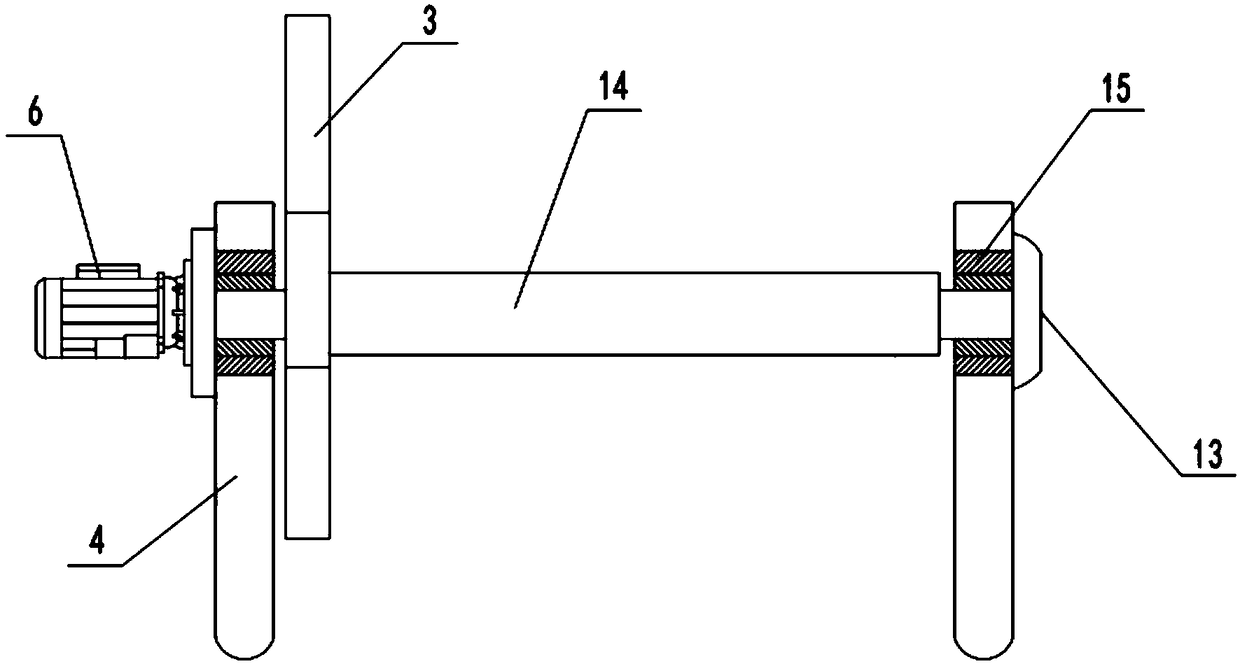
[0026] see image 3 , on the basis of embodiment 1, this embodiment makes the following improvements to embodiment 1, specifically:
[0027] Bearings 15 are installed between the two ends of the rotating drum 14 and the unwinding seat 4, and the unwinding seat 4 without the motor 6 is equipped with a protective cover 13 corresponding to the rotating drum 14. Of course, the protective cover 13 here The cover 13 is detachably connected with the unwinding seat 4, and the specific connection method may be gland or bolt connection, which is not limited here.
[0028] Further, one end of the drum 14 is also fixed with a limiting plate 3, the main purpose of the limiting plate 3 is to limit the side of the cloth roll, and in order to facilitate the roll changing operation, the number of the limiting plate 3 is set Just one.
[0029] In order to facilitate the export of the cloth, one or more guide rollers 10 are installed on the fixed seat 2 .
[0030] The working principle of the...
PUM
 Abstract
Description
Claims
Application Information
 - R&D
- Intellectual Property
- Life Sciences
- Materials
- Tech Scout
- Unparalleled Data Quality
- Higher Quality Content
- 60% Fewer Hallucinations
Browse by: Latest US Patents, China's latest patents, Technical Efficacy Thesaurus, Application Domain, Technology Topic, Popular Technical Reports.
© 2025 PatSnap. All rights reserved.Legal|Privacy policy|Modern Slavery Act Transparency Statement|Sitemap|About US| Contact US: help@patsnap.com