
Solid smelting furnace

A furnace and furnace body technology, applied in the field of heat treatment devices, can solve problems such as difficulty in controlling the heating rate, uneven heating of products, and affecting heating quality, and achieve significant energy saving, improved heating quality, and uniform heating effects

Pending Publication Date: 2018-11-16
苏州工业园区久禾工业炉有限公司
View PDF0 Cites 0 Cited by
  • Summary
  • Abstract
  • Description
  • Claims
  • Application Information

AI Technical Summary

Problems solved by technology

But obviously, since the product to be processed needs to be transported through the roller table in the air duct, the vertically downward hot air or flame will form a turbulent flow in the air duct, making the product temperature rise very uneven and difficult to control the heating rate, affecting the heating quality
And in order to ensure that the aluminum parts are heated evenly, the furnace temperature in the solid melting furnace needs to be kept at about 530°C, and the temperature difference between the upper and lower sides does not exceed 1.5°C to 2°C. Based on the existing heating structure settings in the solid melting furnace, the above requirements cannot be met.

Method used


Image

  • Solid smelting furnace
  • Solid smelting furnace
  • Solid smelting furnace

Examples


Embodiment Construction

[0024] The purpose of the present invention is to provide a solid melting furnace, which can improve the orientation of heat circulation, ensure that the workpiece is heated evenly to improve the heating quality, and at the same time meet the temperature difference in the furnace within 1.5 ° C ~ 2 ° C, the structure is simple, and the performance is better. .

[0025] The technical solutions of the present invention will be clearly and completely described below through specific embodiments. Apparently, the described embodiments are only some of the embodiments of the present invention, but not all of them. Based on the embodiments of the present invention, all other embodiments obtained by persons of ordinary skill in the art without creative efforts fall within the protection scope of the present invention.

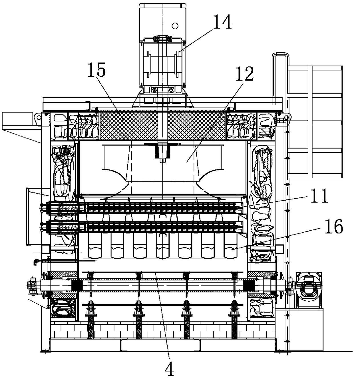
[0026] see Figure 1 ~ Figure 4 As shown, a solid melting furnace, the two sides of the furnace body 1 of the solid melting furnace are respectively provided with an...


PUM


Abstract

The invention discloses a solid smelting furnace. Two sides of a solid smelting furnace body of the solid smelting furnace are provided with a feeding door and a material discharging door respectively, an inner hearth feeding direction of the solid smelting furnace is along the feeding door to the material discharging door, and a workpiece conveying belt capable of placing a workpiece is arrangedbelow the hearth in the feeding direction; a plurality of heating units are arranged in the hearth along the feeding direction correspondingly, each heating unit comprises an air guide device, a heatradiation pipe and a heat circulating fan, wherein the air guide devices are of cover body structures with inward concave parts and arranged above the workpiece conveying belt in a covering mode; theheat circulating fans and the heat radiation pipes are fixed in the concave parts of the air guide devices, moreover, air inlets are formed in the two sides of the inner concave parts of the air guidedevices and communicate with air outlets of the heat circulating fans, hot air blown out by the heat circulating fans is guided through the air guide devices and then is completely blown to the surface of the workpiece placed on the workpiece conveying belt in an ejection mode. According to the solid smelting furnace, the guiding performance of heat circulation can be improved, the uniform heating of the workpiece is guaranteed, and then the heating quality is improved; the heating speed of the workpiece is about 50% faster than the heating speed of a traditional heating mode, so that the efficiency is high, and the remarkable effects of the energy-saving is achieved.

Description

technical field [0001] The invention relates to the technical field of heat treatment devices, in particular to a solid melting furnace. Background technique [0002] Automotive aluminum alloy parts are an inevitable trend of lightweighting new energy vehicles, requiring high strength, rotational bending performance, excellent impact toughness and good fatigue resistance, so there are high requirements for the performance of the materials produced. At present, aluminum alloy materials are widely used in the automotive industry. Aluminum alloys for automotive parts generally need to be melted, refined and added with magnesium, strontium, titanium and other elements for modification and refinement, and then heat treatment to achieve the strength and toughness of aluminum wheels. requirements. At the same time, my country's aluminum auto parts industry has reached a higher level in terms of metamorphism and refinement, but the heat treatment still uses the traditional process,...

Claims


Application Information

Patent Timeline
IPC IPC(8): C21D1/34C21D9/00C22F1/04
CPCC21D1/34C21D9/00C22F1/04
Inventor 吴根土陆金荣余国增
Owner 苏州工业园区久禾工业炉有限公司
Learn More