Electronic test comprehensive instrument and operation method thereof
A technology for electronic testing and resistance testing, applied in multi-tester circuits, etc., can solve the problems of no combination expansion function, user inconvenience, single function, etc., to achieve the effect of convenient and rapid connection, easy portability, and wide application range.
- Summary
- Abstract
- Description
- Claims
- Application Information
AI Technical Summary
Problems solved by technology
Method used
Image
Examples
Embodiment 1
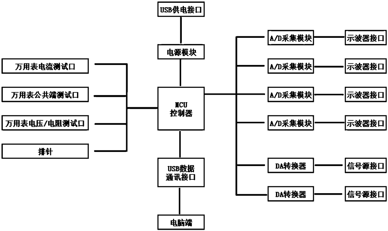
[0043] The invention discloses a comprehensive electronic test instrument, the composition and connection schematic diagram of which is attached figure 1 Shown: a housing with a rectangular parallelepiped structure, and an oscilloscope interface and a signal source interface arranged on one side wall of the housing, and the other symmetrical side wall is provided with a USB data communication interface, a USB indicator light, a configuration switch key, A multimeter voltage / resistance test port, a multimeter common terminal test port, a multimeter current test port, a power indicator light and a USB power supply port, a row of cooling holes are respectively arranged on the upper and lower wall ridges of the other two side walls of the housing, and the housing The upper surface of the body is provided with two sets of pin headers, and the housing is provided with an MCU controller and a power supply module, as well as an A / D sampling module connected to the oscilloscope interfac...
Embodiment 2
[0052] This embodiment relates to a comprehensive electronic testing instrument, and its composition and connection schematic diagram is the same as that of Embodiment 1.
[0053] This embodiment provides a method for operating a comprehensive electronic test instrument. The schematic diagram of its operating mode and principle modules is shown in the attached figure 2 , 3 , 4, 5 and 6, including the following steps:
[0054] Step 1, the USB power supply interface is connected to a power supply, the configuration key is turned on, and the oscilloscope interface, the signal source interface, the multimeter voltage / resistance test port, the multimeter common terminal test port, the multimeter current test port or the pin header are selected to connect to the test equipment;
[0055] Step 2, enter the exclusive interface of each mode on the computer side and click to select the required operation mode, and transmit the operation command to the MCU controller through the USB dat...
PUM
 Abstract
Description
Claims
Application Information
 - R&D
- Intellectual Property
- Life Sciences
- Materials
- Tech Scout
- Unparalleled Data Quality
- Higher Quality Content
- 60% Fewer Hallucinations
Browse by: Latest US Patents, China's latest patents, Technical Efficacy Thesaurus, Application Domain, Technology Topic, Popular Technical Reports.
© 2025 PatSnap. All rights reserved.Legal|Privacy policy|Modern Slavery Act Transparency Statement|Sitemap|About US| Contact US: help@patsnap.com


