Electrical Contact Method and Structure of Rotating Capacitor Rotor in Synchrocyclotron

A cyclotron and rotating capacitor technology, applied in magnetic resonance accelerators, electrical components, accelerators, etc., can solve the problems of low rotational speed of rotating capacitors, cumbersome electrical contact structure, complicated cavity structure design, etc., and achieve good vacuum sealing and guarantee. Electrical contact stability, lower water cooling requirements

Active Publication Date: 2020-03-24
CHINA INSTITUTE OF ATOMIC ENERGY
View PDF8 Cites 0 Cited by
  • Summary
  • Abstract
  • Description
  • Claims
  • Application Information

AI Technical Summary

Problems solved by technology

In the design of a normal temperature synchrocyclotron, the rotation speed of the rotating capacitor is very low, and at the same time, the design of the cavity structure is complicated, and the electrical contact structure between the components is relatively cumbersome.
Conventional synchrocyclotron spin capacitor rotor electrical contact methods exhibit significant limitations in the design of high speed spin capacitors

Method used


Image

  • Electrical Contact Method and Structure of Rotating Capacitor Rotor in Synchrocyclotron
  • Electrical Contact Method and Structure of Rotating Capacitor Rotor in Synchrocyclotron
  • Electrical Contact Method and Structure of Rotating Capacitor Rotor in Synchrocyclotron

Examples


Embodiment Construction

[0034] The present invention will be described in further detail below in conjunction with the accompanying drawings.

[0035] Embodiments, taking a medical synchrocyclotron as an example, introduce the specific structure of the electrical contact structure of the rotating capacitor rotor in the synchrocyclotron, the electrical contact structure of the rotating capacitor rotor is applied to the electrical contact of the rotating capacitor rotor in the synchrocyclotron in the present invention method.

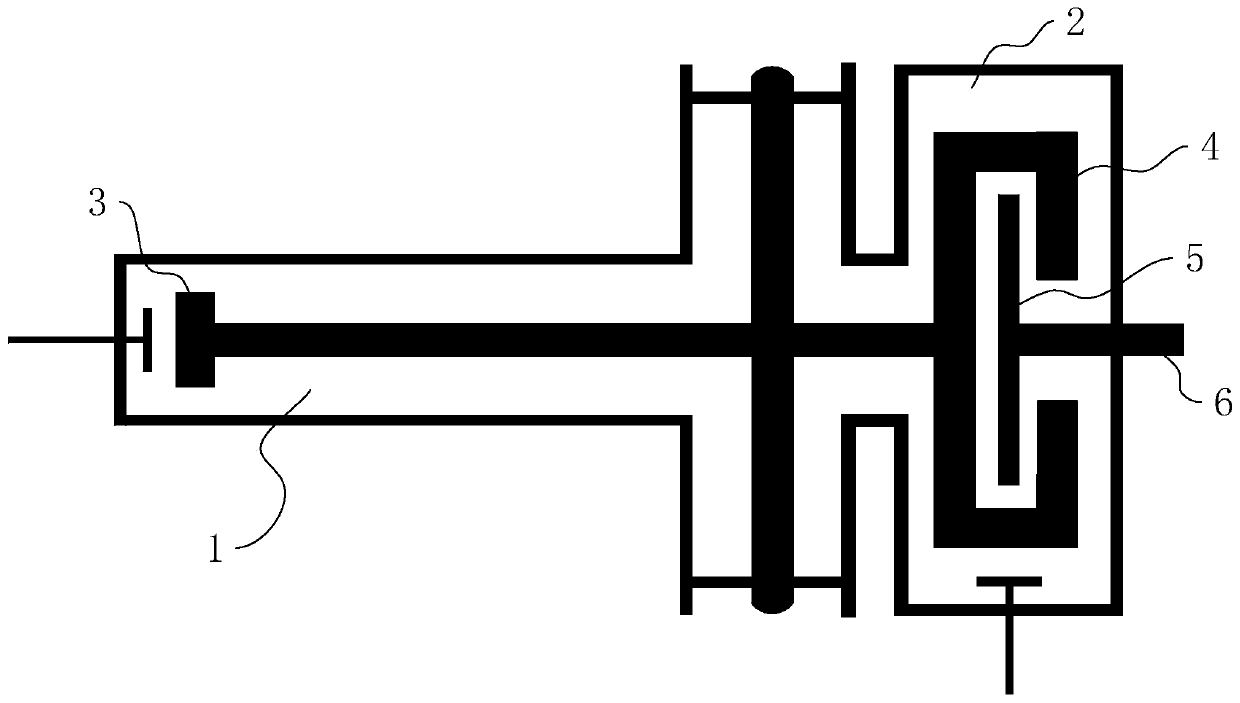
[0036] The synchrocyclotron adopts a variable capacitance method to obtain a frequency of 60MHz-85MHz, and the design value of the modulation frequency is 1kHz. Among them, the ion acceleration time is 0.328ms. figure 1 It is a schematic diagram of the cavity structure of a synchrocyclotron, which adopts a half-wavelength structure; it includes a main vacuum chamber 1 arranged at the head and a capacitor vacuum chamber 2 arranged at the tail. The main vacuum chamber 1 is provid...


PUM


Abstract

The present invention discloses an electric contact structure of rotation of a capacitance rotor in synchrophasotron and a structure thereof. The structure comprises a capacitance vacuum chamber, a capacitance rotor rotationally arranged in the capacitance vacuum chamber and a rotation shaft fixedly connected with one end of the capacitance rotor and configured to drive the rotation of the capacitance rotor. The capacitance rotor comprises a disc portion arranged at the middle portion and a blade portion distributed towards the outer side along the disc portion, the rotation shaft is providedwith an electric connection rotary table having an interval with the disc portion, and an electric connection copper mesh is crimped between the disc portion and the electric connection rotary table;and a planar narrow gap configured to perform high-frequency earthing is arranged between one side, far away from the disc portion, of the electric connection rotary table and the side wall of the capacitance vacuum chamber. The effect of electric contact can be stably achieved in a high-speed rotation condition.

Description

technical field [0001] The invention relates to the field of synchrocyclotrons, and more specifically relates to an electrical contact structure of a rotating capacitor rotor in a synchrocyclotron. Background technique [0002] In order to adapt to the influence of the theory of relativity, the frequency of the cavity decreases gradually during the ion acceleration process of the synchrocyclotron. After the beam is extracted, the frequency of the cavity is quickly returned to the initial acceleration frequency, and the acceleration of the next beam continues. The variation of the cavity frequency of a synchrocyclotron is generally achieved through periodic rotating capacitors. In the design of a normal temperature synchrocyclotron, the rotation speed of the rotating capacitor is very low, and at the same time, the design of the cavity structure is complicated, and the electrical contact structure between the components is cumbersome. In the design of high-speed spinning ca...

Claims


Application Information

Patent Timeline
Patent Type & Authority Patents(China)
IPC IPC(8): H05H13/02
CPCH05H13/02
Inventor 李鹏展张天爵尹蒙纪彬邢建升
Owner CHINA INSTITUTE OF ATOMIC ENERGY
Why Eureka
Try Eureka