Supercharge Your Innovation With Domain-Expert AI Agents!

Orbital clutch and brake assembly for c-arm of imaging system

An imaging system and brake technology, applied in the field of X-ray imaging systems, can solve the problems of complex design, manufacture and assembly, regardless of the change of C-arm

Active Publication Date: 2018-11-20
GENERAL ELECTRIC CO
View PDF11 Cites 0 Cited by
  • Summary
  • Abstract
  • Description
  • Claims
  • Application Information

AI Technical Summary

Problems solved by technology

These units also use two different systems for the brake and clutch, which complicates the design, manufacture and assembly of these units
Additionally, these devices do not account for variations along the C-arm

Method used


Image

  • Orbital clutch and brake assembly for c-arm of imaging system
  • Orbital clutch and brake assembly for c-arm of imaging system
  • Orbital clutch and brake assembly for c-arm of imaging system

Examples


Embodiment Construction

[0018] One or more specific embodiments are described below. In an effort to provide a concise description of these embodiments, it may not be possible for all features of an actual implementation to be described in the specification. It should be understood that during the development of any such actual implementation, such as any engineering or design project, numerous implementation-specific decisions must achieve the developer's specific goals, such as compliance with relevant system constraints that may vary from implementation to implementation and related commercial constraints. Furthermore, it should be appreciated that such development efforts might be complex and time consuming, but would nevertheless be a routine undertaking of design, fabrication, and production for those of ordinary skill in the art having the benefit of this disclosure.

[0019] When introducing elements of various embodiments of the subject matter, the articles "a", "the" mean that there are on...


PUM


Abstract

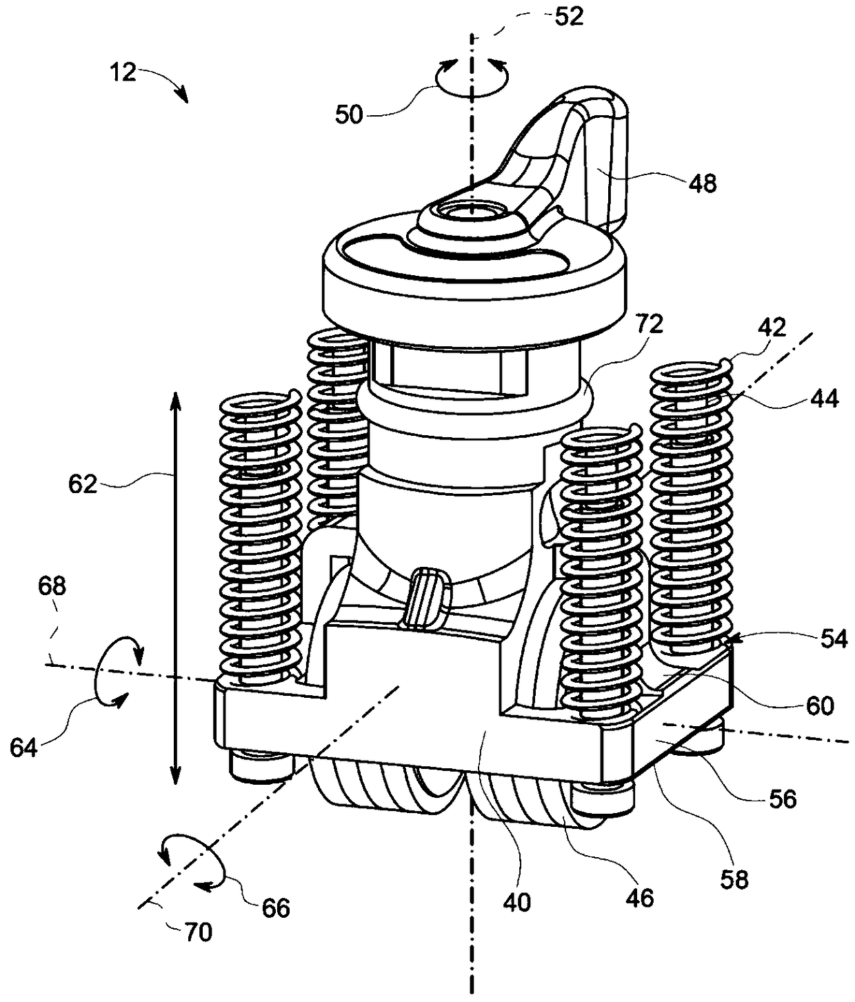
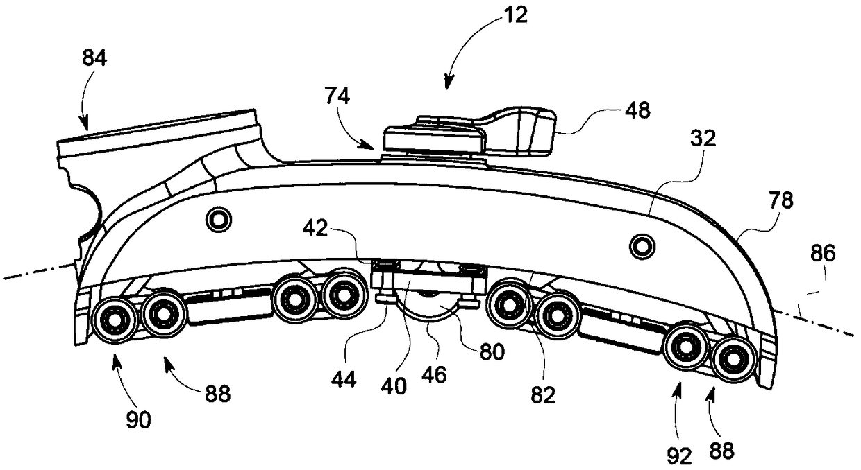
A device is provided. The device includes an orbital clutch and brake assembly configured to couple to a C-arm rotation device that enables the C-arm to rotate in an orbital direction relative to theC-arm rotation device. The orbital clutch and brake assembly includes a housing, a roller, and a brake pad. The roller and brake pad are disposed within the housing. The brake pad is configured to directly contact the roller and to not contact the C-arm when the orbital clutch and brake assembly applies a braking force to the C-arm.

Description

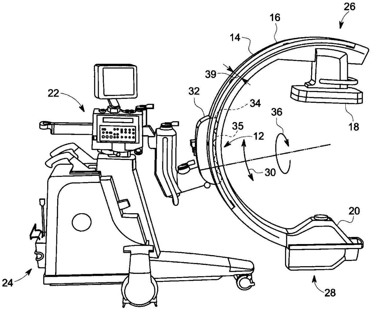
technical field [0001] The subject matter disclosed herein relates to x-ray imaging systems having C-arms, and more particularly to rail clutch and brake assemblies for C-arms. Background technique [0002] Medical diagnostic imaging systems generate images of an object (eg, a patient), for example, by exposure to an energy source (eg, x-rays passing through the patient). The resulting images can be used for a variety of purposes. Often, when a physician takes an x-ray of a patient, it is desirable to take multiple x-rays of one or more portions of the patient's body from multiple different positions and angles, preferably without frequently repositioning the patient. To meet this demand, C-arm X-ray diagnostic equipment has been developed. The term "C-arm" generally refers to an X-ray imaging apparatus having a rigid and / or articulated structural member with an X-ray source and an image detector assembly, the X-ray source and image detector The assemblies are located at ...

Claims


Application Information

Patent Timeline
Patent Type & Authority Applications(China)
IPC IPC(8): A61B6/00
CPCA61B6/4441A61B6/4476A61B6/105F16D67/02F16D49/00F16D65/028A61B6/4405F16D2121/14F16D2125/40
Inventor K.道吉尔达斯J.M.西蒙斯
Owner GENERAL ELECTRIC CO
Features
  • R&D
  • Intellectual Property
  • Life Sciences
  • Materials
  • Tech Scout
  • Unparalleled Data Quality
  • Higher Quality Content
  • 60% Fewer Hallucinations
Learn More