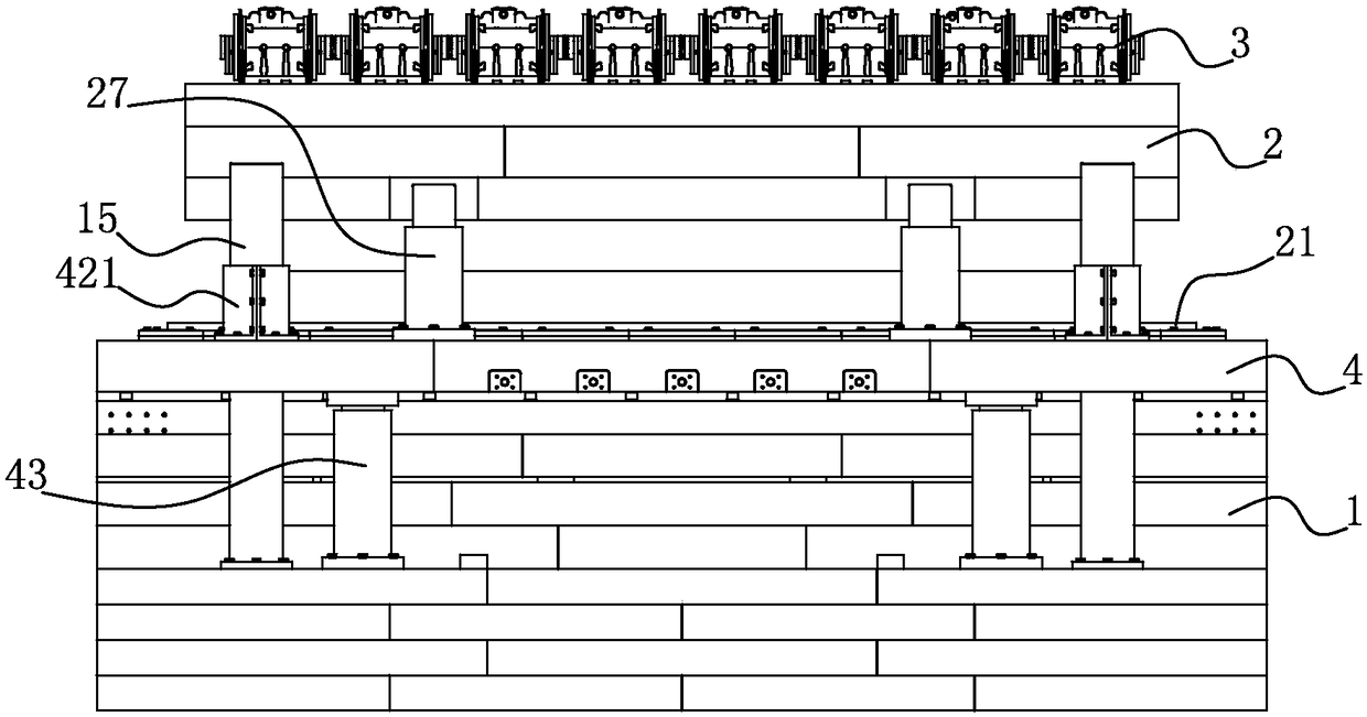
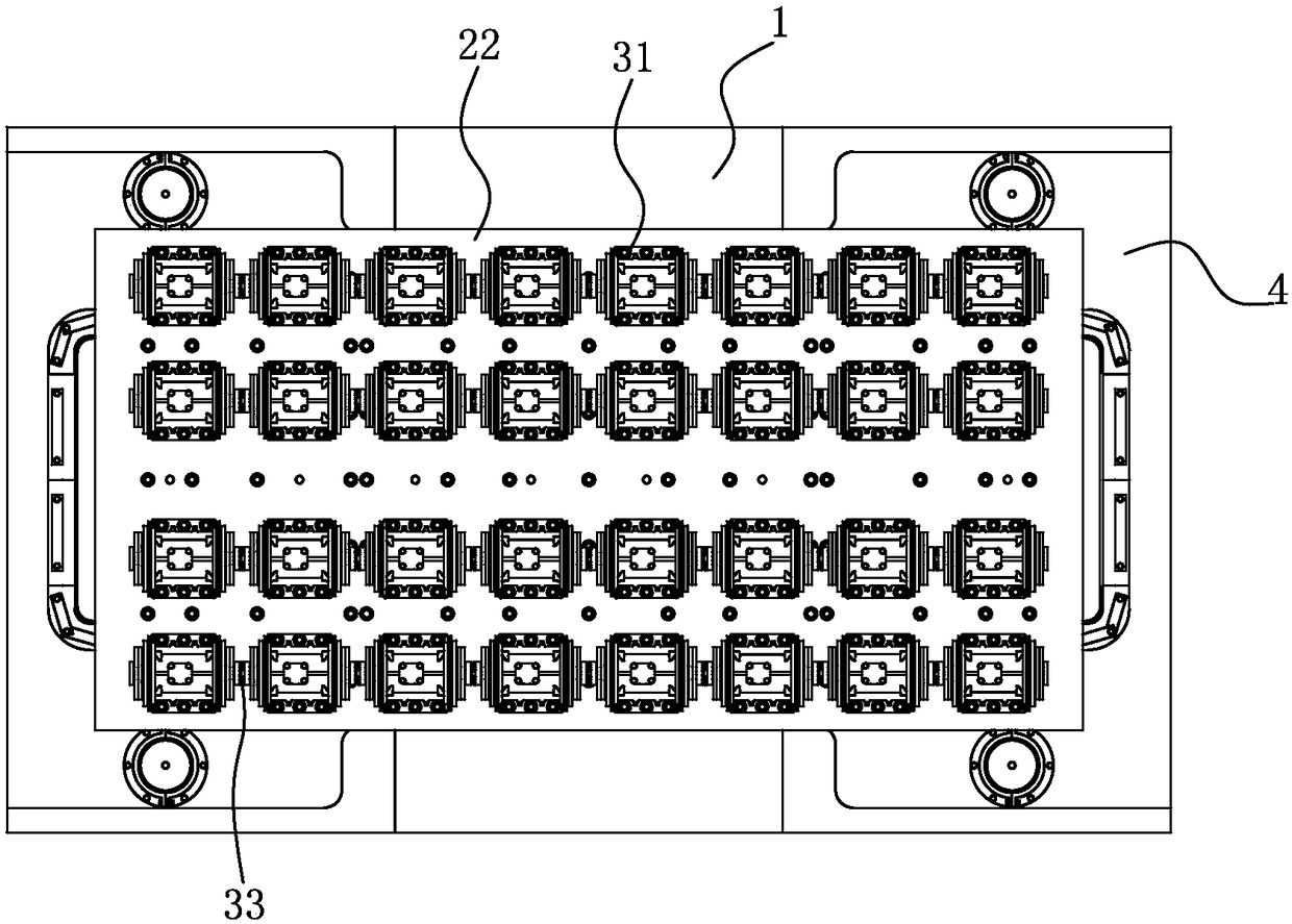
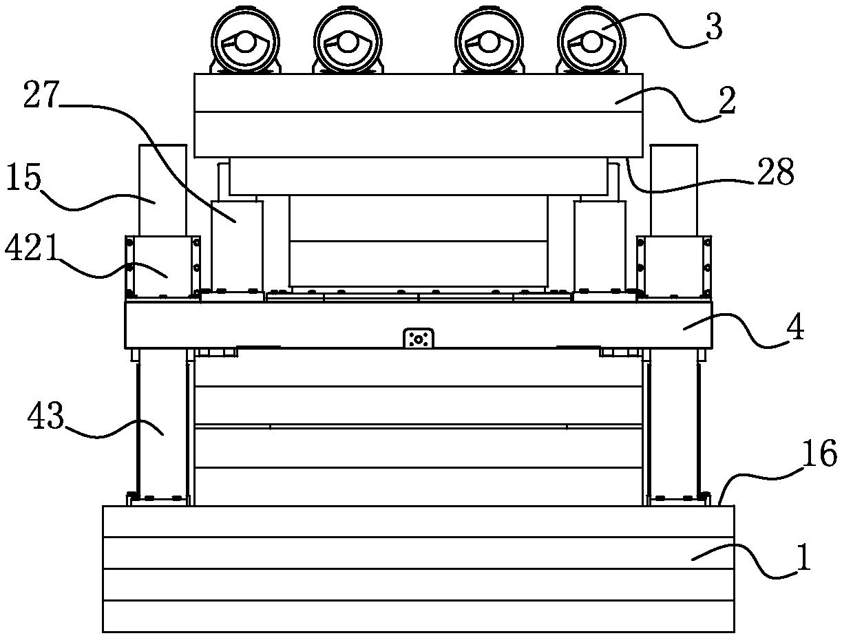
Forming machine for manufacturing vacuum stone

A forming machine and vacuum technology, applied in the direction of forming indenter, etc., can solve the problems of inability to apply sufficient pressure to the plate, affecting the development of vacuum stone forming equipment, damage to the stability of the whole machine, etc., achieving simple structure, fast production speed and stable operation. Effect

Pending Publication Date: 2018-11-20
ANHUI UISTONE GREEN MATERIAL HI TEC CO LTD
View PDF1 Cites 1 Cited by
  • Summary
  • Abstract
  • Description
  • Claims
  • Application Information

AI Technical Summary

Problems solved by technology

In the above technical solution, pressure is applied through hydraulic pressure, and vibration is performed by a vibrating motor, but this pressing plate method has the following disadvantages, because the vibrating motor works with high-frequency vibration, so that the hydraulic system is always in the cycle of pressurization and release , the hydraulic pressure has been in a state of virtual pressure, unable to exert sufficient pressure on the plate
At the same time, the vibration system will cause lasting and continuous damage to the stability of the whole machine.
In order to meet the plate forming, it takes a lot of time to waste
The above technical solutions can be called "pressure + vibration" synthesis method. The problem that the whole industry has been solving is how to combine pressure and vibration force, but this problem has not been solved, which has seriously affected the development of vacuum stone forming equipment. There is always a lack of a mature, large-scale application, and fast forming vacuum stone forming equipment

Method used


Image

  • Forming machine for manufacturing vacuum stone
  • Forming machine for manufacturing vacuum stone
  • Forming machine for manufacturing vacuum stone

Examples


Embodiment Construction

[0028] In order to clearly illustrate the solutions in the present invention, preferred embodiments are given below and detailed descriptions are given in conjunction with the accompanying drawings. The following description is merely exemplary in nature and is not intended to limit the application or uses of the present disclosure. It should be understood that throughout the drawings, corresponding reference numerals indicate like or corresponding parts and features.

[0029] The vacuum stone of the present invention is a brand-new plate material, which includes granular aggregates of different particle sizes and filling unit bodies with reference volumes, and the filling unit bodies are made of fine-grained solid particle fillers and liquid fillers, so The surface of the solid particle filler has a flexible liquid-filled film formed by filling the liquid filler, the particle aggregates of each particle size are filled and bonded to each other, and the gaps between the partic...


PUM


Abstract

The invention discloses a forming machine for manufacturing a vacuum stone. The forming machine comprises a base, a heavy hammer and drivers, wherein the heavy hammer is installed on the base, and thedrivers are used for driving the heavy hammer; the base is provided with a material carrying area, the heavy hammer is used for beating the material carrying area, and a hammer plate is arranged at the bottom of the heavy hammer, and a material carrying belt is arranged on the base; the forming machine is further comprises a template, a hollow out part is formed in the middle of the template, thehammer plate is located in the hollowed out part, a multilayer lip-shape sealing rings are arranged at the top of a mold frame, and the lip-shape sealing rings abut against the side wall of the hammer plate; and an annular sealing ring is arranged at the bottom of the mold frame, the annular sealing ring abuts against the material carrying belt, the mold frame, the hammer plate and the material carrying belt form a vacuum cavity for wrapping materials, and a vacuum air suction channel is formed in the mold frame. According to the forming machine, a sealing structure is arranged at a vacuum stone material mixing position, only a vacuum stone mixing material is subjected to vacuum treatment, the vacuumizing speed is higher, and the sealing structure is simpler.

Description

technical field [0001] The invention relates to a molding machine for making vacuum stones. Background technique [0002] The vacuum stone in the present invention is a new product, which is prepared using the principle of the Magdeburg hemisphere. The vacuum stone is closer to natural stone in nature, and the overall performance of the vacuum stone is also close to natural stone. The specific description of the vacuum stone of the present invention can be referred to the previous patent application of the inventor. However, it is a technical problem to cooperate with the pressurization system and the vibration system of the vacuum stone production equipment, which makes the existing equipment complicated to manufacture, unstable in production operation, high in maintenance and repair rate, and unable to meet the production requirements of the vacuum stone. For example, the utility model patent with the Chinese patent No. CN201120319813.9 discloses an artificial quartz ston...

Claims


Application Information

Patent Timeline
Patent Type & Authority Applications(China)
IPC IPC(8): B28B3/04
CPCB28B3/04
Inventor 杨绍良杨专书胥焱杨绍忠曹琪
Owner ANHUI UISTONE GREEN MATERIAL HI TEC CO LTD
Why Eureka
Try Eureka