Eureka AIR delivers breakthrough ideas for toughest innovation challenges, trusted by R&D personnel around the world.

Hydraulicdrive type podded propulsor for testing

A thruster and test technology, applied in the direction of ship propulsion, propulsion components, ship components, etc., can solve the problems of restricting the motor in the pod propeller, time-consuming and labor-intensive installation of the motor, and small space volume, so as to avoid strong electricity and The effects of weak current interference, easy maintenance of concentricity, and simple installation process

Active Publication Date: 2018-11-20
HARBIN ENG UNIV
View PDF4 Cites 4 Cited by
  • Summary
  • Abstract
  • Description
  • Claims
  • Application Information

AI Technical Summary

Problems solved by technology

However, there are also many problems in the test process of the pod propeller model. For example, the interior space of the pod propeller model is small, and it is impossible to install a high-power motor. Therefore, the motor in the pod propeller is severely limited. The selection and setting of test conditions
Secondly, it is time-consuming and labor-intensive to install the motor in the pod propeller cabin. In order to maintain the concentricity of the motor shaft and the cabin axis, there are cumbersome processes of multiple installations and multiple disassembly.
At the same time, the magnetism inside the motor also interferes with the weak current of the balance circuit, which causes sudden changes in the measurement data during the test, which seriously affects the progress of the entire test and the accuracy of data measurement.
The motor is installed inside the cabin. Once there is a problem with the motor, the entire device must be disassembled to repair the motor. The workload is very heavy, which is not conducive to equipment maintenance
In addition, installing the motor inside the pod propeller cabin will undoubtedly increase the length of the pod propeller cabin, which limits the development of the pod propeller to miniaturization and affects the application range of the pod propeller

Method used


Image

  • Hydraulicdrive type podded propulsor for testing
  • Hydraulicdrive type podded propulsor for testing
  • Hydraulicdrive type podded propulsor for testing

Examples


Embodiment Construction

[0025] The following examples describe the present invention in more detail.

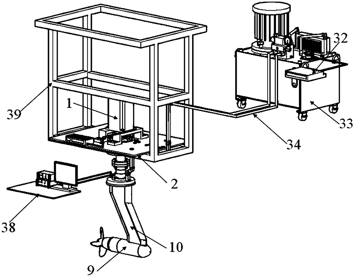
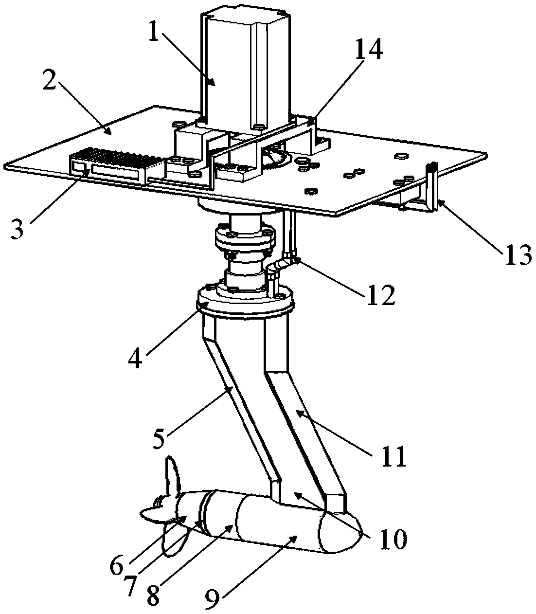
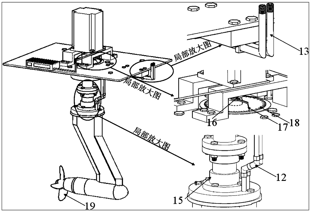
[0026]The hydraulically driven pod thruster used in the test of the present invention includes a pod thruster unit and a hydraulic control system. The pod propulsion unit is composed of a measuring unit, a combined housing and a steering gear. The measuring unit is the force measuring and speed measuring part of the pod propulsion unit, which can measure the overall force of the propeller and the pod unit and the rotational speed of the shaft. The main It consists of a propeller measuring balance, a pod unit overall force measuring balance, a propeller measuring balance line, a balance line conversion head and a photoelectric speedometer. The propeller measuring balance is fixed in the front pod shell through the bearing pressure sleeve, radial thrust bearing and spring retaining ring, the propeller measuring balance line passes through the front pod shell and the rear pod shell, and passes through ...


PUM


Abstract

The invention provides a hydraulic drive type podded propulsor for testing. The hydraulic drive type podded propulsor for testing comprises a podded propulsor unit and further comprises a hydraulic control system; a propeller drive of the podded propulsor unit is a hydraulic motor; L-shaped rigid oil pipes are mounted on an oil inlet and an oil outlet of the hydraulic motor; the L-shaped rigid oilpipes are connected with a rigid oil pipe disposed along a pod supporting rod through a rigid oil pipe joint; the rigid oil pipe passes through a flange plate of the pod supporting rod; the rigid oilpipe on an upper end of the flange plate of the pod supporting rod is connected with a universal rotating joint; the universal rotating joint is then connected to one section of the rigid oil pipe; the hydraulic control system comprises a hydraulic pump station and a hydraulic motor controller; an oil outlet and an oil return port of the hydraulic pump station are connected with the last sectionof the rigid oil pipe through a flexible oil pipe. The hydraulic drive type podded propulsor for testing is suitable for development and research of the podded propulsor and has the advantages of small size, good stability, light weight and convenient assembly and disassembly.

Description

technical field [0001] The present invention relates to a ship propeller, in particular to a pod propeller. Background technique [0002] With the advent of slewing propulsion devices, pod propulsion systems were gradually developed. The pod propulsion unit can be regarded as an azimuth propulsion device, and its electric motor is located in the pod. Compared with other slewing methods, the advantage of pod propulsion is that it requires less space and saves the traditional complex shafting, which also makes the wake field of the ship more uniform and improves the overall propulsion efficiency of the propeller. In addition, the pod propeller can realize 360-degree continuous rotation, which makes it easier for the ship to operate under emergency conditions such as emergency braking and reversing. The overall maneuverability of the ship is optimized, and it has been widely used. The research and development of the pod propeller has also attracted the attention of more and m...

Claims


Application Information

Patent Timeline
IPC IPC(8): B63H5/125
CPCB63H5/125B63H2005/1254
Inventor 郭春雨徐佩叶礼裕李凤来骆婉珍张承森田太平
Owner HARBIN ENG UNIV
Why Eureka
Eureka Blog
Learn More