Air tightness detecting device and detecting method for movement process of high speed train

A technology for air tightness detection and high-speed EMU, which is applied in the direction of using liquid/vacuum degree for liquid tightness measurement, and by measuring the acceleration and deceleration rate of fluid, etc. To achieve the effect of saving time and manpower, and simple structure

Active Publication Date: 2018-11-20
LANZHOU JIAOTONG UNIV
View PDF5 Cites 3 Cited by
  • Summary
  • Abstract
  • Description
  • Claims
  • Application Information

AI Technical Summary

Problems solved by technology

[0003] The technical problem to be solved by the present invention is to overcome the shortcomings of the existing high-speed EM...

Method used


Image

  • Air tightness detecting device and detecting method for movement process of high speed train
  • Air tightness detecting device and detecting method for movement process of high speed train
  • Air tightness detecting device and detecting method for movement process of high speed train

Examples


Embodiment Construction

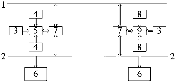
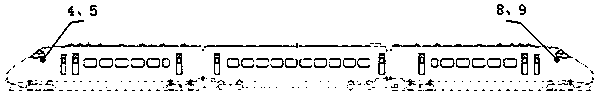
[0033] combine figure 1 and figure 2 , to describe in detail the airtightness detection method and device during high-speed EMU movement.

[0034] Such as figure 1 and figure 2 As shown, a high-speed EMU moving air tightness detection device includes a head position single-chip microcomputer 5 and a head position air pressure transmitter 4 installed at the head of the EMU, and the head position MCU 5 is connected to two sets of head position air pressure transmitters 4. The head position air pressure transmitter 4 is connected to the head position single-chip microcomputer 5 and transmits the air pressure information outside the car and inside the car to the head position single-chip microcomputer 5, and the rear position single-chip microcomputer 9 installed at the rear of the EMU and the rear position air pressure transmitter 8, the single-chip microcomputer 9 at the rear of the car is connected to two groups of air pressure transmitters 8 at the rear of the car, the ai...


PUM


Abstract

The invention provides an air tightness detecting device and detecting method for a movement process of a high speed train. The device includes two air pressure transmitters and one single chip microprocessor disposed on a head locomotive of the high speed train and two air pressure transmitters and one single chip microprocessor disposed on a tail locomotive of the high speed train. The device isadvantaged in that the structure is simple and air pressure leakage information can be displayed in real time. When air pressure leakage occurs, the position of an air pressure leakage point can be calculated; data can be stored in a CCU(Central Control Unit) and can be transmitted to a DMI (Driver-Machine Interface) through an MVB (Multifunction Vehicle Bus) connected with the CCU. The detectionmethod is that when air pressure leakage occurs, the single chip microprocessors on the head locomotive and the tail locomotive send air pressure abnormal values and abnormal moments measured by theair pressure transmitters to the CCU, calculate the air pressure leakage position according to time difference in combination with vehicle speed, vehicle length and air pressure propagation rate and gives real time alarm and display in the DMI. At the same time, the CCU can be started during in-factory maintenance of the high speed train and information of the air pressure leakage position can becalled, so that a large amount of time and labor can be saved in air tightness check.

Description

technical field [0001] The invention relates to the technical field of air tightness detection of high-speed train sets, in particular to an air tightness test device and a detection method for high-speed train sets in motion. Background technique [0002] With the rapid development of my country's high-speed railway passenger transport, the requirements for the reliability and comfort of vehicle operation are getting higher and higher. The airtightness of the train has a great influence on the change of the pressure inside the train, and will ultimately determine the comfort level of the pressure inside the train. However, when the existing high-speed EMU is running, when an air pressure leak occurs, it cannot give an alarm and display the location information of the air pressure leak, and when the existing high-speed EMU is overhauled in the depot, the airtight leak point detection mainly uses The methods of hearing, touching, and soapy water are relatively primitive and ...

Claims


Application Information

Patent Timeline
IPC IPC(8): G01M3/26
CPCG01M3/26
Inventor 李建国梅元贵贺云鹏
Owner LANZHOU JIAOTONG UNIV
Why Eureka
Try Eureka