
Post-treatment process of high-gloss formed cutter

A technology for forming tools and post-processing, applied in the direction of manufacturing tools, grinding workpiece supports, metal processing equipment, etc., can solve the problems of inability to polish and polish the tools, inability to guarantee the passivation effect, uneven tool passivation, etc., to save dullness passivation time, guaranteed passivation effect, and improved surface finish

Inactive Publication Date: 2018-11-23
WUXI GUOHONG MEASURING & CUTTING TOOLS
View PDF4 Cites 0 Cited by
  • Summary
  • Abstract
  • Description
  • Claims
  • Application Information

AI Technical Summary

Problems solved by technology

The passivation of walnut parts is to submerge the tool into the walnut powder, and then through the revolution and rotation of the tool to make the uniform friction and collision between the cutting edge of the tool and the walnut powder to achieve the purpose of passivation, but the buried depth of the tool is different when the walnut powder is used for passivation. During the passivation process, the impact and extrusion of the cutting edge will be different, which will inevitably make the passivation of the tool uneven, which directly affects the passivation effect of the tool, and the longer the blade length, the greater the impact on the passivation effect. The larger the size, and the walnut powder passivation can only be aimed at the cutting edge, and cannot polish the whole tool
Manual grinding is to use a file to directly squeeze and grind the cutting edge according to the experience of the workers to achieve the purpose of passivation. Since pure manual grinding also has uneven force, the passivation effect cannot be guaranteed

Method used


Image

  • Post-treatment process of high-gloss formed cutter
  • Post-treatment process of high-gloss formed cutter
  • Post-treatment process of high-gloss formed cutter

Examples


Embodiment Construction

[0021] The preferred embodiments of the present invention will be described below in conjunction with the accompanying drawings. It should be understood that the preferred embodiments described here are only used to illustrate and explain the present invention, and are not intended to limit the present invention.

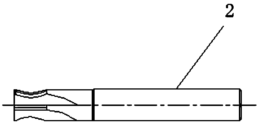
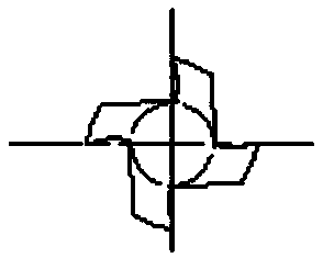
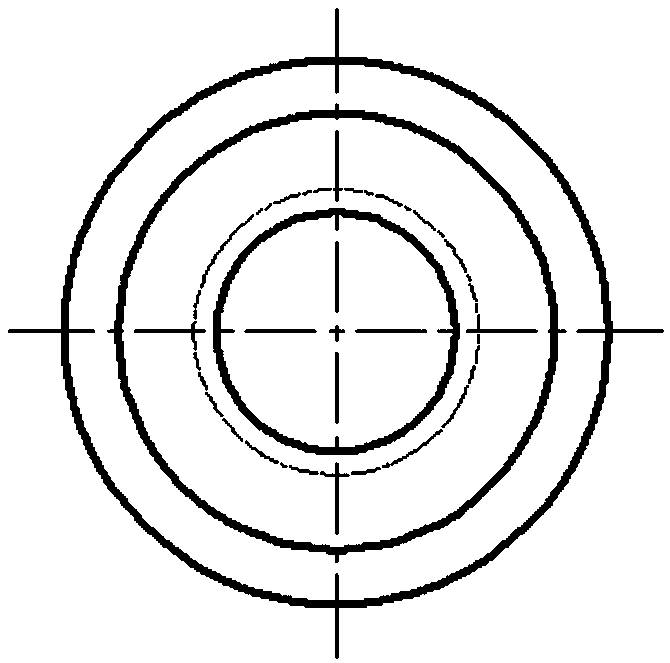
[0022] Such as Figure 1-6 As shown, a post-processing process for high-gloss forming tools includes the following steps: 1) Design a fixture 1, a tool hole is arranged in the center of the fixture, and the part directly involved in polishing on the fixture is set into a tool contour shape according to the distribution of the knife edge, and the tool is guaranteed The distance between each position and the fixture is equal, and four evenly distributed decompression holes are added on the fixture;

[0023] 2) Abrasives for polishing are configured. The abrasives for tool fluid polishing are made of a polymer semi-solid carrier with viscoelasticity, softness and cutti...


PUM


Abstract

The invention discloses a post-treatment process of a high-gloss formed cutter. The post-treatment process comprises the following steps that a cutter hole is formed in the center of a clamp, the part, directly participating in polishing, of the clamp is arranged to be in a cutter profile shape according to distribution of cutter edges, it is ensured that the distances between all the positions ofthe cutter and the clamp are equal, and four evenly-distributed pressure relief holes are additionally formed in the clamp; an abrasive material for cutter fluid polishing is made of a macromoleculesemi-solid carrier and abrasive grains in a mixed configuration mode according to the ratio of 3:2; and the fluid polishing process is conducted through the steps that (1) a power switch of a polisheris turned on, the configured abrasive material for cutter fluid polishing is put into a lower cylinder of the polisher, the clamp is fixed to a worktable, and the to-be-passivated cutter is fixed tothe clamp; (2) the polishing time and the abrasive material pressure are set, a machine is started, pistons in an upper cylinder and the lower cylinder make reciprocating movement at a constant speed,thus the abrasive grains flow through the cutter and edge openings uniformly, and polishing passivation is completed; and (3) after being polished, the cutter is taken out, and replaced with a new to-be-polished cutter. Overall force bearing is uniform and constant, the passivation effect is ensured, and the passivation time is saved.

Description

technical field [0001] The invention belongs to the technical field of grinding tool passivation, and in particular relates to a post-treatment process for high-gloss forming tools. Background technique [0002] Tool passivation can prolong the service life of the tool, improve the processing efficiency and precision of the machine tool, and reduce the surface roughness of the workpiece to be processed. After the passivation treatment, the cutting edge of the tool becomes very smooth, which greatly reduces chipping and improves the surface finish of the workpiece. [0003] At present, the existing passivation process on the market is two kinds of passivation with walnut powder and manual polishing. The passivation of walnut parts is to submerge the tool into the walnut powder, and then through the revolution and rotation of the tool to make the uniform friction and collision between the cutting edge of the tool and the walnut powder to achieve the purpose of passivation, bu...

Claims


Application Information

Patent Timeline
IPC IPC(8): B24B3/00B24B41/06B24B31/116
Inventor 于忠光郑立健张继波费建红
Owner WUXI GUOHONG MEASURING & CUTTING TOOLS
Learn More