Building material lifting machine capable of achieving convenient and rapid carrying

A technology for building materials and hoists, applied in the direction of cranes, etc., can solve the problems of increasing the tediousness of work, unable to adjust the lifting grip, and single adjustable orientation, and achieves enhanced overall structural stability, strong overall structural stability, The effect of reducing labor complexity

Pending Publication Date: 2018-11-23
重庆启晟建材有限公司
View PDF0 Cites 4 Cited by
  • Summary
  • Abstract
  • Description
  • Claims
  • Application Information

AI Technical Summary

Problems solved by technology

[0004] The object of the present invention is to provide a building material hoist that is easy to transport quickly, so as to solve the problem that the currently used building material hoist proposed by the above background technology cannot place items and has poor stability, which is not conducive to the stable lifting work of the hoist. After long-term use, looseness occurs uniformly, which is not conducive to the long-term effective work of the crane. The adjustable position is single, and the adjustment method is not easy to operate. According to the specific material of the building materials and the scattered situation of the building materials, the appropriate lifting and grabbing method is selected, which increases the complexity of the work, reduces the efficiency of the work, and is not conducive to the long-term use of the crane.

Method used


Image

  • Building material lifting machine capable of achieving convenient and rapid carrying
  • Building material lifting machine capable of achieving convenient and rapid carrying
  • Building material lifting machine capable of achieving convenient and rapid carrying

Examples


Embodiment 1

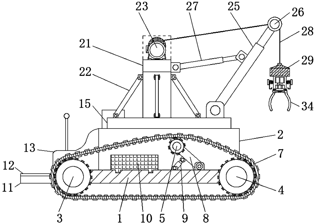
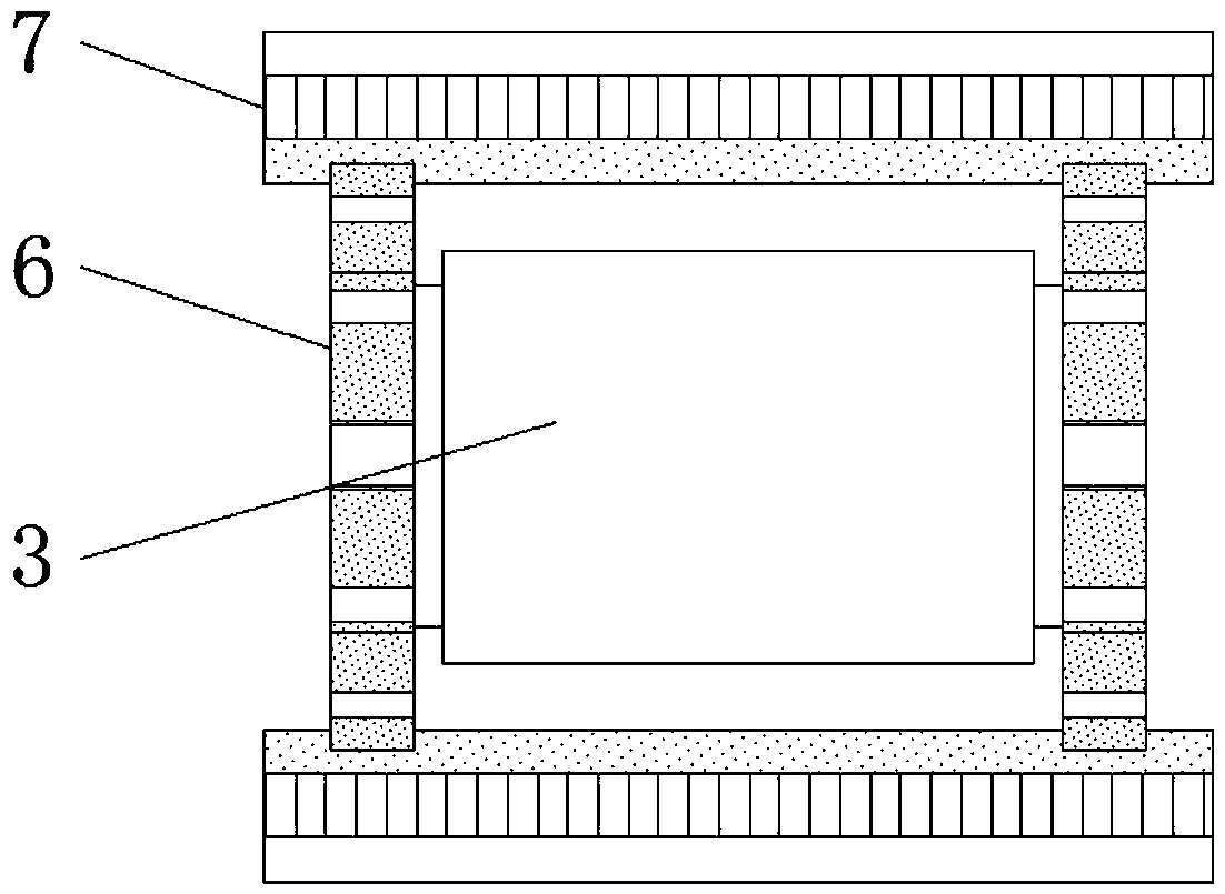
[0030] Example 1, such as figure 2 The outer sides of the middle driving wheel 3, the guide wheel 4 and the supporting sprocket 5 are equipped with meshing discs 6, and the interlocking discs 6 form a linkage structure through the track 7, and the meshing between them is used to facilitate the transmission of the track 7. as well as Figure 4 The middle storage box 14 is a detachable structure on the power box 2, and the storage box 14 includes a box cover 1401, a connecting plate 1402, an insertion rod 1403 and a handle 1404, and the outside of the bottom of the box cover 1401 is provided with a handle 1404, and the handle 1404 The rear side is provided with a plunger 1403, and the plunger 1403 is installed below the handle 1404, which is convenient for storing the tools that need to be used during the work or maintenance of the crane. The storage box 14 is magnetically connected to the bottom plate 1 through the connecting plate 1402 , and between the storage box 14 and th...

Embodiment 2

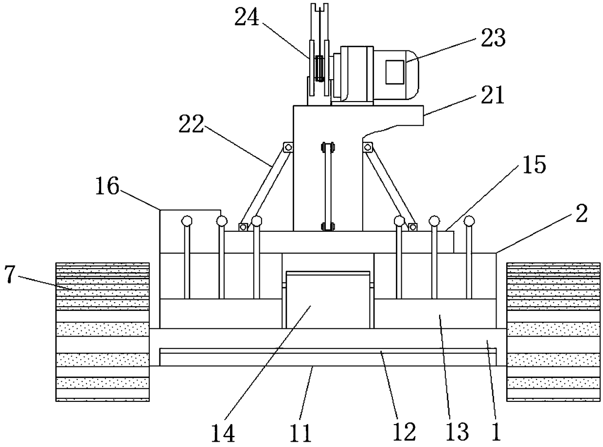
[0031] Example 2, such as Figure 5 There are two middle cabinets 16, and the cabinets 16 are installed on the outside of the chassis 15 and the top of the support column 21 respectively, and the outer walls of the cabinets 16 are arranged with ventilating grooves 17 at equal intervals, which ensures that the cabinet 16 has a pair of internal first drive motors 18 and The heat dissipation work of the second drive motor 23 is conducive to ensuring the long-term work of the first drive motor 18 and the second drive motor 23. In addition, the transmission plate 20 includes a connecting plate 2001 and a driven plate 2002, and a driven plate 2001 is installed below the connecting plate 2001. The disc 2002, the connecting disc 2001 and the driving disc 19 are engaged and connected, and the driven disc 2002 is engaged and connected with the chassis 15, and the chassis 15 is a rotating structure above the power box 2, so as to facilitate the operation of the rotation of the chassis 15 ...

Embodiment 3

[0032] Example 3, such as Figure 7 The middle transmission plate 32 is a telescopic structure inside the shell 30, and the transmission plate 32 is connected with the handle 34 through the transmission rod 33, and the structure between the handle 34 and the shell 30 is a rotating structure, which is convenient for grabbing building materials and is convenient for carrying out use, and figure 2 Among them, the reel 24 is respectively connected with the reel 26 and the electromagnetic device 29 through the first rope 28, and the electromagnetic device 29 and the shell 30 are disassembled. The cross-sectional shape and structure of the column 35 is a "T"-shaped structure, and the fixed column 35 is connected with the hook 37 through the second rope 36, which is convenient for adopting different grabbing methods according to different building materials, so that the crane can be more suitable for lifting work , which reduces labor cumbersomeness and is conducive to improving li...


PUM


Abstract

The invention discloses a building material lifting machine capable of achieving convenient and rapid carrying. The building material lifting machine comprises a bottom plate, a supporting platform, abase plate, a telescopic rod and fixing columns, wherein a power box is installed at the upper end of the bottom plate, a supporting wheel rod is connected to the lower portion of a chain supportingwheel, and the supporting platform is installed at the left end of the bottom plate; a driving disc is installed at the output end of a first driving motor, a supporting column is arranged on the bottom plate, and the telescopic rod is located on the right side of the supporting column; and a first rope is connected to the outer side of a wire lapping disc in a lap-joint manner, a handle is arranged on the outer side of each transmission rod, and the fixing columns are installed on the outer side of a shell. According to the building material lifting machine capable of achieving convenient andrapid carrying, storage of articles is convenient to achieve, the whole structure is high in stability, and movement is convenient to achieve, so that long-term efficient use of a moving mechanism isguaranteed, and position adjustment of the handles in the space is convenient to achieve. Multiple building material grabbing modes are adopted, so that the building material lifting machine is morepractical, the labor complexity is reduced, and improving of the lifting efficiency is facilitated.

Description

technical field [0001] The invention relates to the technical field of building material hoisting, in particular to a building material hoist that is convenient for rapid handling. Background technique [0002] With the continuous improvement of people's living standards, the construction industry has developed particularly hot in recent years. In the construction industry, material hoists play a vital role. Easy-to-use hoists can bring great convenience to work. It saves time for work and improves the efficiency of workers' work. [0003] At present, when many cranes are working, the working range is relatively limited, and it is impossible to place the items of the staff, and some tools cannot be placed. The traditional moving method mostly uses pulleys to move, and the stability of pulleys is not as good as that of crawlers, but crawlers After long-term use, its moving mechanism is easy to relax, which is not conducive to use. The traditional hoist cannot adjust the heig...

Claims


Application Information

Patent Timeline
IPC IPC(8): B66C23/62B66C23/36B66C23/64
CPCB66C23/36B66C23/62B66C23/64
Inventor 应广大
Owner 重庆启晟建材有限公司
Why Eureka
Try Eureka