Chemical loop power generation device based on casing pipe reactor

A technology of casing reactor and power generation device, which is applied in steam engine device, gas turbine device, machine/engine, etc., can solve the problems of single function of equipment or system, high equipment investment cost and operating cost, and improve utilization rate and save equipment. Cost and operating cost, good effect of feasibility

Active Publication Date: 2018-11-23
WUHAN UNIV OF TECH
View PDF3 Cites 3 Cited by
  • Summary
  • Abstract
  • Description
  • Claims
  • Application Information

AI Technical Summary

Problems solved by technology

However, the existing chemical looping combustion capture carbon dioxide equipment or system has a single function, and the equipment investment cost and operation cost are high

Method used


Image

  • Chemical loop power generation device based on casing pipe reactor
  • Chemical loop power generation device based on casing pipe reactor

Examples


Embodiment Construction

[0015] In order to better understand the present invention, the present invention will be further described below in conjunction with the accompanying drawings and specific embodiments.

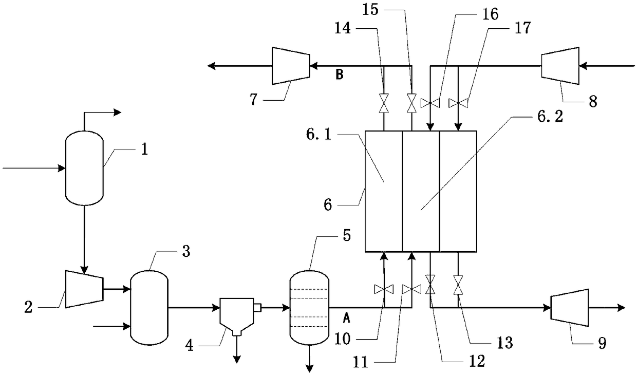
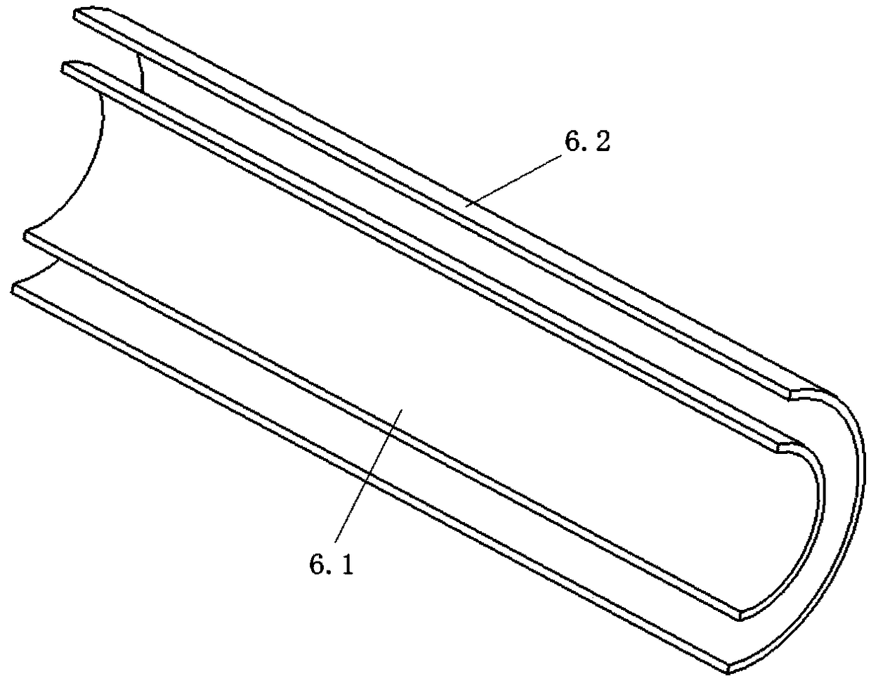
[0016] Such as figure 1 A chemical chain power generation device based on a casing reactor is shown, including an air separation machine 1, a first air compressor 2, a casing reactor 6, a first turbine 7, a second air compressor 8 and a second A turbine 9, the inlet of the air separator 1 is communicated with a fresh air source, the first outlet of the air separator 1 is communicated with a nitrogen pipeline, and the second outlet of the air separator 1 is communicated with the inlet of the first air compressor 2 through a pipeline , the outlet of the first air machine 2 communicates with the inlet of the sleeve reactor 6 through the pipeline A, the outlet of the sleeve reactor 6 communicates with the inlet of the first turbine 7 through the pipeline B, and the outlet of the first turbine 7 ...


PUM


Abstract

The invention discloses a chemical loop power generation device based on a casing pipe reactor. The device comprises an air separating machine, a first air compressor, the casing pipe reactor, a firstturbine, a second air compressor and a second turbine. An inlet of the air separating machine communicates with an air source, a first outlet of the air separating machine communicates with a nitrogen pipeline, a second outlet of the air separating machine communicates with an inlet of the first air compressor, an outlet of the first air compressor communicates with an inlet of the casing pipe reactor, an outlet of the casing pipe reactor communicates with an inlet of the first turbine, and an outlet of the first turbine communicates with a waste heat boiler; an inlet of the second air compressor communicates with a fresh air source, an outlet of the second air compressor communicates with the inlet of the casing pipe reactor through a pipeline, an outlet of the casing pipe reactor communicates with an inlet of the second turbine, an outlet of the second turbine communicates with the outlet of the waste heat boiler, and a reduction oxygen carrier is arranged in the casing pipe reactor. The chemical loop power generation device has the beneficial effects that the casing pipe reactor is used, acting power generation is carried out while heat is transmitted, and energy consumption ofcarbon dioxide capturing is obviously reduced.

Description

technical field [0001] The invention relates to the technical field of carbon dioxide capture by chemical looping combustion, in particular to a chemical looping power generation device based on a sleeve reactor. Background technique [0002] Chemical looping combustion (CLC) technology is a new type of energy utilization technology based on the capture of carbon dioxide by circulating oxygen carriers. Compared with traditional post-combustion capture technology, the technical feature is high-purity CO 2 Internal separation, high energy conversion efficiency, low nitrogen oxide emissions, simple operation and so on. The chemical looping combustion capture carbon dioxide technology makes full use of the heat in the oxygen carrier regeneration process to reduce energy loss; the product after the reduction reaction is high-purity CO 2 , to reduce CO 2 Separation costs. However, the existing chemical looping combustion capture carbon dioxide equipment or system has a single f...

Claims


Application Information

Patent Timeline
Patent Type & Authority Applications(China)
IPC IPC(8): F01D15/10F01K11/02F02C6/00F02C3/26F02C3/04
CPCF01D15/10F01K11/02F02C3/04F02C3/26F02C6/00
Inventor 史彬温芳吴二东
Owner WUHAN UNIV OF TECH
Why Eureka
Try Eureka