Thrust bearing, rotor system and control method of thrust bearing

A technology of thrust bearings and rotors, applied in bearings, bearing assemblies, bearing components, etc., to achieve strong anti-disturbance ability and improve bearing capacity

Pending Publication Date: 2018-11-23
刘慕华
View PDF11 Cites 15 Cited by
  • Summary
  • Abstract
  • Description
  • Claims
  • Application Information

AI Technical Summary

Problems solved by technology

[0005] The invention provides a thrust bearing, a rotor system and a control method of the

Method used


Image

  • Thrust bearing, rotor system and control method of thrust bearing
  • Thrust bearing, rotor system and control method of thrust bearing
  • Thrust bearing, rotor system and control method of thrust bearing

Examples


Embodiment 1

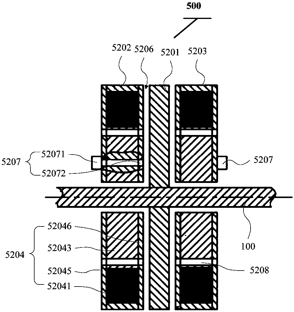
[0090] Such as Figure 1 to Figure 7 As shown, the thrust bearing 500 is used to be installed on the rotating shaft 100, and the thrust bearing 500 includes:

[0091] A thrust plate 5201, the thrust plate 5201 is fixedly connected to the rotating shaft 100, and the thrust plate 5201 is provided with a first magnetic component;

[0092] And, the first stator 5202 and the second stator 5203 passing through the rotating shaft 100, the first stator 5202 and the second stator 5203 are respectively arranged on opposite sides of the thrust plate 5201;

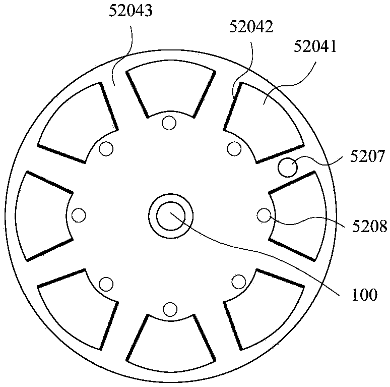
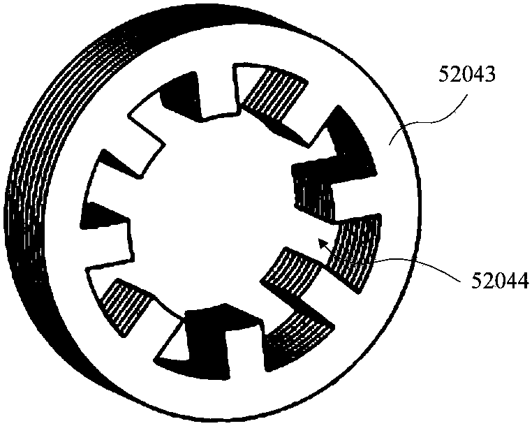
[0093] In the first stator 5202 and the second stator 5203, each stator includes a magnetic bearing 5204, and the magnetic bearing 5204 is provided with a plurality of second magnetic components capable of generating magnetic force with the first magnetic component along the circumferential direction, and the magnetic bearing 5204 There is a bearing gap 5206 between the thrust plate 5201, and the thrust plate 5201 can move in the axi...

Embodiment 2

[0137] An embodiment of the present invention provides a rotor system, including:

[0138] A rotating shaft, the shaft body of which is an integrated structure, and the rotating shaft is arranged horizontally;

[0139] A motor, a compressor and a turbine arranged on the rotating shaft in sequence;

[0140] And, a thrust bearing and at least two radial bearings arranged on the rotating shaft;

[0141]Wherein, the thrust bearing is arranged at a preset position on the side of the turbine close to the compressor, and the preset position is such that the center of gravity of the rotor system is located at the at least two radial bearings The position between the two radial bearings that are farthest apart.

[0142] In the embodiment of the present invention, the thrust bearing is the thrust bearing provided in this application.

[0143] In the embodiment of the present invention, the thrust bearing is a bearing used to limit the movement of the rotating shaft in the axial direc...

Embodiment 3

[0159] An embodiment of the present invention provides a rotor system, including:

[0160] A rotating shaft, the shaft body of the rotating shaft is an integrated structure, and the rotating shaft is arranged vertically;

[0161] A motor, a compressor and a turbine arranged on the rotating shaft in sequence;

[0162] And, a thrust bearing and at least two radial bearings arranged on the rotating shaft;

[0163] Wherein, the thrust bearing is arranged at a preset position on the side of the turbine close to the compressor, and the preset position is such that the center of gravity of the rotor system is located at the at least two radial bearings The position between the two radial bearings that are farthest apart.

[0164] In the embodiment of the present invention, the thrust bearing is the thrust bearing provided in this application.

[0165] In the embodiment of the present invention, the thrust bearing is a bearing used to limit the movement of the rotating shaft in the...


PUM


Abstract

The invention provides a thrust bearing, a rotor system and a control method of the thrust bearing. The thrust bearing comprises a thrust disc, a first stator and a second stator, wherein the thrust disc is fixed on a rotating shaft, and a first magnetic part is arranged on the thrust disc; the first stator and the second stator are arranged on the rotating shaft in a penetrating mode, and the first stator and the second stator are arranged on the two opposite sides of the thrust disc respectively; each stator comprises a magnetic bearing, a plurality of second magnetic parts are arranged on the magnetic bearing in the circumferential direction, bearing gaps are formed between the magnetic bearings and the thrust disc, and the thrust disc can move in the axial direction of the rotating shaft under the action of the magnetic force between the first magnetic part and the plurality of the second magnetic parts; and dynamic pressure generating grooves are formed in the thrust disc or the first stator and the second stator. According to the thrust bearing, the rotor system and the control method of the thrust bearing, bearing clearances and magnetic bearings are arranged in the thrust bearing, so that the thrust bearing forms gas and magnetic hybrid thrust bearings, the gas bearings and the magnetic bearings can work cooperatively, so that the dynamic performance and the stability of the thrust bearing under a high-speed running state can be improved.

Description

technical field [0001] The invention relates to the technical field of bearings, in particular to a thrust bearing, a control method and a rotor system. Background technique [0002] A gas turbine mainly includes three major components: a compressor, a combustor, and a turbine. After the air enters the compressor, it is compressed into high-temperature and high-pressure air, and then supplied to the combustion chamber for mixed combustion with fuel, and the high-temperature and high-pressure gas generated expands in the turbine to perform work. When the rotor rotates at high speed, the rotor will be subjected to force in the axial direction. In order to limit the axial movement of the rotating shaft, thrust bearings need to be installed in the rotor system. Traditional thrust bearings are common contact bearings. As the rotor speed increases, especially when the rotor speed exceeds 40,000 revolutions per minute, ordinary contact bearings can no longer meet the requirements...

Claims


Application Information

Patent Timeline
IPC IPC(8): F16C32/04F16C41/00F01D5/02F02C7/06
CPCF01D5/02F02C7/06F16C32/0402F16C32/0444F16C32/0446F16C32/0474F16C41/00F16C2360/23
Inventor 靳普
Owner 刘慕华
Why Eureka
Try Eureka