Direct current furnace condensate recovery system and method based on high and low pressure condensate flash tanks

A technology of drain expansion and drain recovery, which is applied in the field of drain recovery system of non-starting circulating pump DC furnace, can solve the problem of complex start-up system of recirculation pump, high investment of start-up system of start-up drain heat exchanger, relatively high loss of working medium and heat Large and other problems, to achieve the effect of increasing initial investment and operation and maintenance costs, reducing the amount of water replenishment and fuel consumption, and reducing the loss of working fluid and heat

Active Publication Date: 2018-11-23
SHANDONG ELECTRIC POWER ENG CONSULTING INST CORP
View PDF4 Cites 6 Cited by
  • Summary
  • Abstract
  • Description
  • Claims
  • Application Information

AI Technical Summary

Problems solved by technology

Improper hydrophobic treatment will often cause the destruction of the original heat balance in the condenser, resulting in increased back pressure, affecting the output of the unit, and also causing problems such as shock, vibration, damage to the condenser tube, and shell separation.
[0009] To sum up, in the prior art, for the simple atmospheric expansion type starting system, the separated steam is discharged into the atmosphere, and the loss of working fluid and heat is relatively large, and the composite atmospheric expansion type starting system will lose part of the working fluid during the starting process And most of the heat, the start-up system of the hydrophobic heat exchanger ha

Method used


Image

  • Direct current furnace condensate recovery system and method based on high and low pressure condensate flash tanks
  • Direct current furnace condensate recovery system and method based on high and low pressure condensate flash tanks
  • Direct current furnace condensate recovery system and method based on high and low pressure condensate flash tanks

Examples


Example Embodiment

[0057] Example 1:

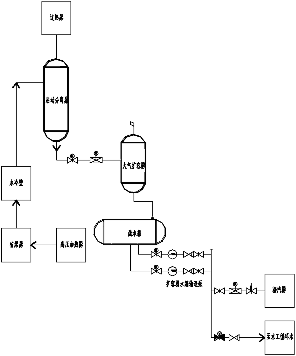
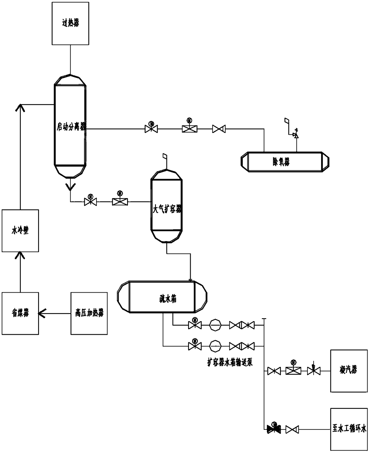
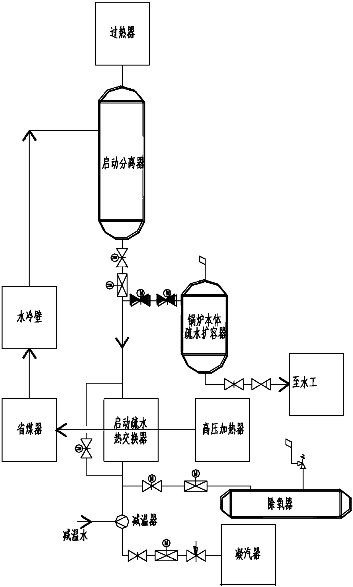
[0058] In a typical implementation of this application, such as figure 1 As shown, a drainage recovery system for a DC boiler without a start-up circulating pump based on a high and low pressure drainage expansion vessel is provided. The system includes a separator 1, a separator water storage tank 2, a high pressure drainage expansion vessel 3, a low pressure drainage expansion vessel 4, and The oxygenator 5, the condenser 6, the unit drainage tank 7 and other steam users 8; the high-pressure drainage expansion vessel 3 and the low-pressure drainage expansion vessel 4 are the integral structure of the drainage expansion vessel and the water tank.

[0059] The separator 1 is connected to the separator water storage tank 2, and the separator water storage tank 2 is connected to the high-pressure drainage expansion vessel 3, and the pressure of the high-pressure drainage expansion vessel 3 is between the pressure of the start separator 1 and the pressure of the dea...

Example Embodiment

[0068] Example 2:

[0069] Taking the cold start of the unit as an example, the operation mode of the non-starting circulating pump direct-flow boiler drainage recovery system based on the high-pressure drainage expansion vessel and the low-pressure drainage expansion vessel proposed in Example 1 is described in detail as follows:

[0070] In the initial stage of unit startup, before ignition, cold cleaning is required. After the water supply is completed, the boiler is cleaned in cold state. The feed water passes through the economizer, furnace water wall, water wall outlet mixing header, separator 1 and separator water storage tank. 2. Then drain to the high-pressure drain expansion vessel 3 through the draining water level regulating valve 11. If the iron content in the water at the outlet of the separator storage tank is greater than 1000 μg / L, the drain passes through the regulating valve 6 21 and enters the low-pressure drain expansion vessel 4, after starting the drain pump ...


PUM


Abstract

The invention discloses a direct current furnace condensate recovery system and method based on high and low pressure condensate flash tanks. The direct current furnace condensate recovery system comprises a separator, a separator water storage tank, the high pressure condensate flash tank, the low pressure condensate flash tank, a deaerator, a condenser, a unit drain tank, other steam users and astarting condensate pump. Condensate of the separator passes through the separator water storage tank to enter the high pressure condensate flash tank. Steam in the high pressure condensate flash tank is conveyed to the deaerator and other steam users for heat recovery, redundant steam is discharged to the low pressure condensate flash tank and is discharged to the atmosphere through an exhaust pipe. When water is qualified, the condensate is discharged to the deaerator for heat recovery, or redundant condensate is discharged to the condenser, and the working medium is recovered. When water is unqualified, the condensate is discharged into the low pressure condensate flash tank and is discharged to the unit drain tank through the starting condensate pump.

Description

technical field [0001] The invention relates to a drainage recovery system for a once-through furnace, in particular to a drainage recovery system and method for a direct-flow furnace without a start-up circulation pump based on a high-low pressure drainage expansion vessel. Background technique [0002] At present, supercritical and ultra-supercritical units have been called the main units of thermal power plants in my country. Since the once-through furnace has no steam drum and natural circulation loop, it is necessary to maintain a feed water flow rate of about 30% of the rated evaporation from the ignition to ensure the minimum flow rate of the water wall, and the boiler enters the once-through load at about 30% of the rated load condition. , so before entering the DC load, the boiler has a large amount of working fluid and heat to be discharged through the start separator and the start separator water storage tank. The current common startup systems are as follows: ...

Claims


Application Information

Patent Timeline
IPC IPC(8): F22B37/50F22D11/00
CPCF22B37/50F22D11/00
Inventor 曹洪振祁金胜李官鹏蒋莉王妮妮李琳
Owner SHANDONG ELECTRIC POWER ENG CONSULTING INST CORP
Why Eureka
Try Eureka