Fault detection method and system

A fault detection and detection technology, applied in the direction of measuring devices, optical testing flaws/defects, instruments, etc., can solve the problems of low efficiency and poor accuracy of appearance detection

Inactive Publication Date: 2018-11-23
周东杰
View PDF8 Cites 7 Cited by
  • Summary
  • Abstract
  • Description
  • Claims
  • Application Information

AI Technical Summary

Problems solved by technology

[0006] The purpose of the present invention is to provide a fault detection method and system to solve

Method used


Image

  • Fault detection method and system
  • Fault detection method and system
  • Fault detection method and system

Examples


Embodiment 1

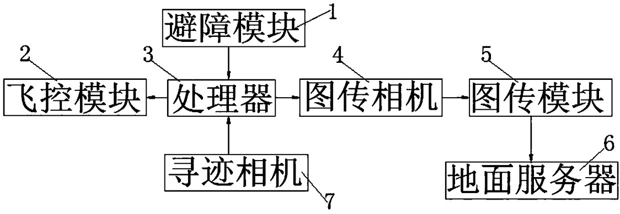
[0109] The fault detection system of the present invention includes an unmanned aerial vehicle and a ground server 6 connected to it in communication; The tracking camera 7; the obstacle avoidance module 1, the flight control module 2, the image transmission camera 4, and the tracking camera 7 are all connected in communication with the processor 3; the image transmission camera 4 and the ground server 6 are all connected to each other The image transmission module 5 is connected in communication; the obstacle avoidance module 1 is used to provide the distance information from the UAV to the obstacle; the image transmission camera 4 is used to scan the detected object according to the preset scanning direction and Taking pictures; the image transmission module 5 is used to send the collected image information to the ground server 6; the flight control module 2 is used to run the tracking algorithm, so that the UAV can fly according to the preset path; The ground server 6 is us...

Embodiment 2

[0117] Further, on the basis of embodiment 1:

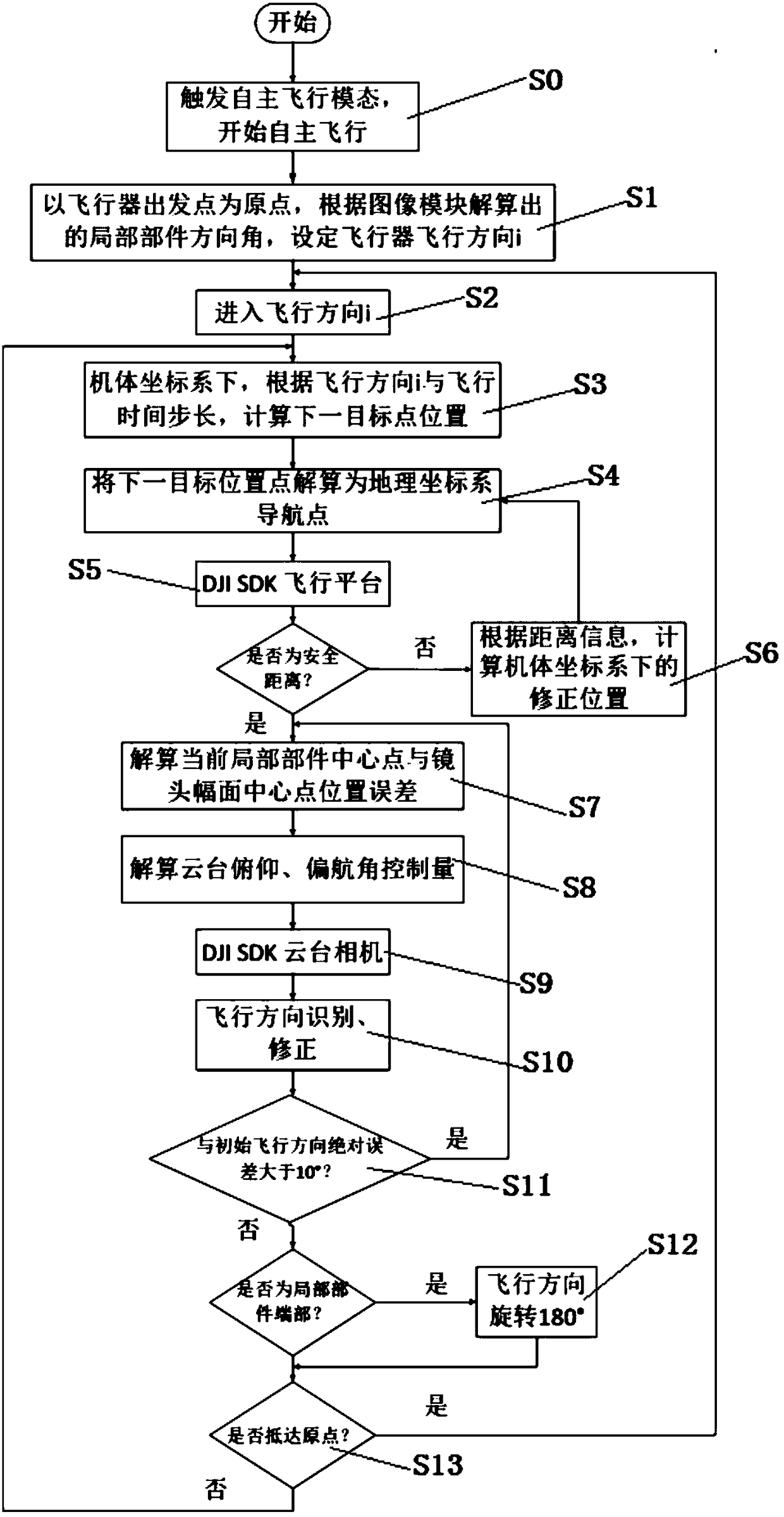
[0118] The fault detection method of the present embodiment 2 is used for the fault detection system, comprising steps:

[0119] The unmanned aerial vehicle flies to the front of the detected object to ensure that the tracking camera 7 can photograph the complete detected object;

[0120] When the unmanned aerial vehicle first traces, the processor 3 runs a full contour extraction algorithm to complete the extraction of the entire contour of the detected object, and outputs the azimuth of each local part of the detected object and the imaging plane;

[0121] According to the obstacle distance information provided by the obstacle avoidance module 1 and the azimuth angle of the imaging plane provided by the tracking camera 7, the scanning direction is determined, and the image transmission camera 4 scans the local parts of the detected object according to the scanning direction. to scan;

[0122] The processor 3 runs a local cont...

Embodiment 3

[0127] Further, on the basis of embodiment 2:

[0128] When the unmanned aerial vehicle first traces, the processor 3 runs a full contour extraction algorithm to complete the extraction of the entire contour of the detected object, and outputs the azimuths of each local part of the detected object and the imaging plane including:

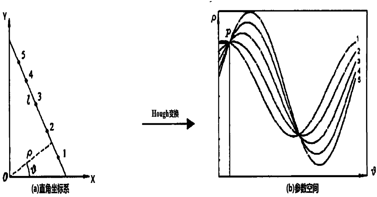
[0129] The full contour detection of the detected object is realized by combining the Canny edge detection operator with the Hough transform;

[0130] The azimuth angle between each local component and the imaging plane is calculated by Hough transform.

[0131] The Canny edge detection operator smoothes the image through a Gaussian filter, and implements non-extreme value suppression to obtain the edge of the image;

[0132] The Canny edge detection operator is an operator that integrates image smoothing, edge enhancement and detection. The basic principle of this operator is to select a Gaussian filter to smooth the image to be processed; and pe...


PUM


Abstract

The invention relates to a fault detection system comprising an unmanned plane and a ground server communicating with the unmanned plane; the unmanned plane comprises an obstacle avoidance module, a flight control module, a processor, an image transmission camera, an image transmission module, and a tracking camera; the obstacle avoidance module, the flight control module, the image transmission camera and the tracking camera respectively communicate with the processor; the image transmission camera and the ground server respectively communicate with the image transmission module. The fault detection method comprises the following steps: the unmanned plane flies to a position right in front of a detected object; the processor uses a full contour extraction algorithm to extract the detectedobject contour and determines a scanning direction; the image transmission camera scans a local part of the detected object according to the scanning direction and takes photos; the processor runs alocal contour extraction algorithm and outputs an azimuth between the local part and an imaging plane; the flight control module runs a tracking algorithm, the image transmission camera collects imageinformation of the local part and sends same to the ground server, and the ground server runs a deep nerve network algorithm to analyze the image information, thus finishing fault diagnosis classification.

Description

technical field [0001] The invention relates to the technical field of fault detection, in particular to a fault detection method and system. Background technique [0002] Large-scale mechanical equipment is prone to appearance damage during use, so it is necessary to regularly inspect the equipment. However, due to the large size of the equipment or the high placement, the difficulty of inspection is increased, resulting in low inspection efficiency and poor inspection effect. [0003] The traditional detection method uses manual observation through the telescope to check whether the equipment is in good condition. Due to the large size of the equipment, it is not easy to choose the observation point and the work intensity of the observers is high; One of them, but it is necessary to set up certain equipment to cooperate with personnel to work at heights, the cost is high and safety accidents are frequent. [0004] At present, the more convenient way is to use UAV to shoot...

Claims


Application Information

Patent Timeline
IPC IPC(8): G01D21/00G01N21/95G01N21/88
CPCG01D21/00G01N21/8851G01N21/95G01N2021/8887
Inventor 周东杰刘畅
Owner 周东杰
Why Eureka
Try Eureka