Full Stokes polarization imaging element and preparation method thereof

A polarization imaging and component technology, applied in the field of full Stokes polarization imaging components and their preparation, can solve the problems of incompatibility, low optical performance, complex process, etc., and achieve the effect of great application value and high technical effect

Active Publication Date: 2018-11-23
SHANGHAI INST OF OPTICS & FINE MECHANICS CHINESE ACAD OF SCI
View PDF4 Cites 5 Cited by
  • Summary
  • Abstract
  • Description
  • Claims
  • Application Information

AI Technical Summary

Problems solved by technology

[0006] The purpose of the present invention is to provide a full-Stokes polarization imaging element and its preparation method. The polarization element can realize real-time full-polarization imaging, and has high transm...

Method used


Image

  • Full Stokes polarization imaging element and preparation method thereof
  • Full Stokes polarization imaging element and preparation method thereof
  • Full Stokes polarization imaging element and preparation method thereof

Examples


Embodiment 1

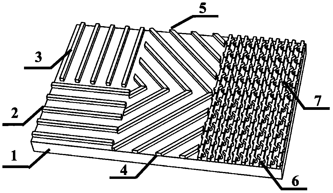
[0037] figure 1 It is a structural schematic diagram of embodiment 1 of the full-Stokes polarization imaging element, including a dielectric wire grid structure with a 0° orientation, a dielectric wire grid structure with a 90° orientation, a dielectric wire grid structure with a 45° orientation, and a dielectric wire grid structure with a 135° orientation structure, left-handed rotation symmetric chiral medium structure and right-handed rotational symmetric chiral medium structure.

[0038] This element is made by following steps:

[0039] (1) A layer of silicon is grown on the surface of silicon dioxide by electron beam evaporation or chemical vapor deposition;

[0040] (2) Use a glue leveler to coat a layer of electron beam photoresist negative glue on the silicon layer;

[0041] (3) Use electron beam exposure and development technology to obtain wire grids with different orientations of 0°, 90°, 45° and 135° according to specific parameters and photoresist structure patt...

Embodiment 2

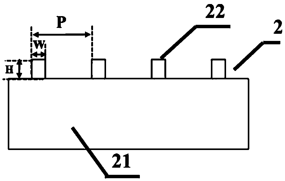
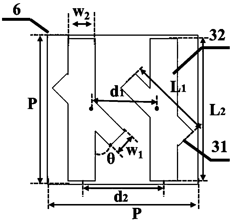
[0049] The parameters of the rotationally symmetrical chiral structure are: the thickness H of the dielectric structure layer is 0.26 μm; the period P of the rotationally symmetrical chiral structure is 1.0 μm, the arm length L1 is 0.5 μm, the arm length L2 is 1.0 μm, and the distance between the two arms L1 The distance d1 is 0.21 μm, the distance d2 between the two arms L2 is 0.24 μm, the arm width W1 is 0.12 μm, the arm width W2 is 0.17 μm, and the angle θ between the two arms is 40°; the period of the dielectric wire grid structure P is 1.0 μm, and the wire grid width W is 0.2 μm.

Embodiment 3

[0051] The parameters of the rotationally symmetrical chiral structure are: the thickness H of the dielectric structure layer is 0.29 μm; the period P of the rotationally symmetrical chiral structure is 1.2 μm, the arm length L1 is 0.8 μm, the arm length L2 is 1.07 μm, and the distance between the two arms L1 The distance d1 is 0.27 μm, the distance d2 between the two arms L2 is 0.33 μm, the arm width W1 is 0.21 μm, the arm width W2 is 0.26 μm, and the angle θ between the two arms is 55°; the period of the dielectric wire grid structure P is 1.2 μm, and the wire grid width W is 0.3 μm.


PUM

PropertyMeasurementUnit
Thicknessaaaaaaaaaa
Thicknessaaaaaaaaaa

Abstract

The invention provides a full Stokes polarization imaging element. The full Stokes polarization imaging element comprises a light transmissive substrate and a dielectric structure layer on the light transmissive substrate; the dielectric structure layer is composed of a super pixel unit array; the super pixel unit comprises four dielectric wire gating structures with different orientations and tworotationally symmetric chiral structures with different rotational directions. The full Stokes polarization imaging element can be fabricated through the processes such as electron beam exposure anddevelopment techniques, reactive ion beam etching and the like; the full Stokes polarization imaging element can realize real-time full polarization imaging; the transmittance of the linear polarizerin the full Stokes polarization imaging element is 99% or more at 1.7 to 1.8 [Mu]m, the extinction ratio is 20 dB or more, and the maximum of the extinction ratio is 55 dB; the highest circular polarization dichroism can reach 96.8% at 1.75 [Mu]m; meanwhile, the full Stokes polarization imaging element has simple structure and excellent performance, and has wide source of raw materials and simplepreparation, which has great application value in the field of polarization imaging.

Description

technical field [0001] The invention relates to a polarization optical element, in particular to a full-Stokes polarization imaging element and a preparation method thereof. Background technique [0002] In recent years, with the continuous development of polarization technology, it plays an increasingly important role in target recognition and detection. According to the Fresnel formula, when an object emits, reflects, scatters and transmits electromagnetic waves, it will generate specific polarization information related to its own characteristics. There will be differences in the polarization information of different objects, even the same object in different states. Polarization detection can provide more information about the target than traditional intensity detection and spectral detection. Polarization imaging technology has become the third imaging technology besides traditional intensity imaging and spectral imaging, and has gradually attracted more and more atte...

Claims


Application Information

Patent Timeline
IPC IPC(8): H01L27/146
CPCH01L27/14625H01L27/14685
Inventor 胡敬佩朱玲琳张方曾爱军黄惠杰
Owner SHANGHAI INST OF OPTICS & FINE MECHANICS CHINESE ACAD OF SCI
Why Eureka
Try Eureka