Ultra-wideband band-pass filter structure with wide stop band and high selectivity

A band-pass filter, high selectivity technology, applied in the direction of waveguide devices, electrical components, circuits, etc., can solve the problems of high operating frequency, poor performance, and narrow bandwidth of band-pass filters, and achieve simple structure and high structural performance Excellent, good design freedom effect

Active Publication Date: 2018-11-23
NAT UNIV OF DEFENSE TECH
View PDF5 Cites 16 Cited by
  • Summary
  • Abstract
  • Description
  • Claims
  • Application Information

AI Technical Summary

Problems solved by technology

[0006] Aiming at the problems of high operating frequency, narrow bandwidth and poor performance of existing substrate-integrated waveguide (SIW)-based bandpass filters, an ultra-wideband bandpass filter structure with wide stopband and high selectivity is proposed

Method used


Image

  • Ultra-wideband band-pass filter structure with wide stop band and high selectivity
  • Ultra-wideband band-pass filter structure with wide stop band and high selectivity
  • Ultra-wideband band-pass filter structure with wide stop band and high selectivity

Examples


Embodiment Construction

[0025] The present invention will be further described below in conjunction with the accompanying drawings and embodiments.

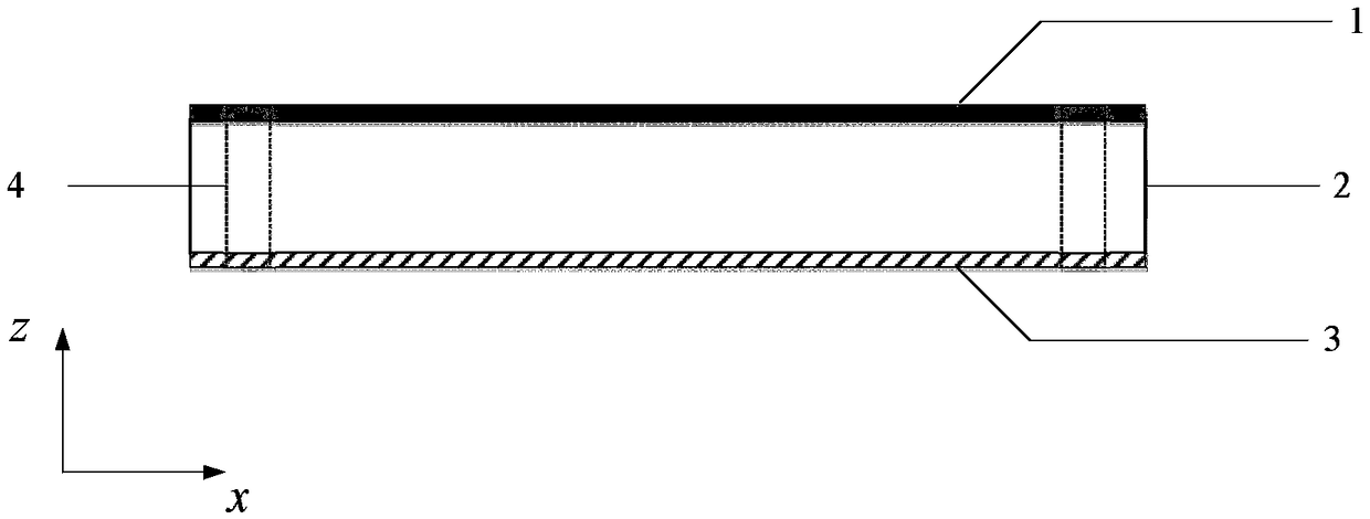
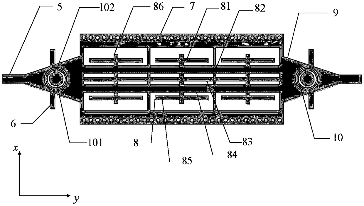
[0026] like figure 1 , figure 2As shown, the present invention provides an ultra-wideband bandpass filter structure with wide stopband and high selectivity, comprising a dielectric substrate 2, a metal foil layer 1 attached to the upper surface of the dielectric substrate, covering the dielectric The metal ground layer 3 on the lower surface of the substrate; the front side of the metal foil layer 1 is a combined shape composed of a cone and a rectangle, and the combined shape is composed of a microstrip transmission line 5, an open circuit stub 6, an upper surface of the substrate integrated waveguide 7, The compact microstrip resonance unit 8, the tapered microstrip gradient line 9 and the complementary split resonant ring 10, the metal foil layer 1 is connected to the metal ground layer 3 through two rows of metallized through holes 4 that run thro...


PUM


Abstract

The invention belongs to the field of passive microwave solid-state circuits, in particular to an ultra-wideband band-pass filter structure with a wide stop band and high selectivity. The filter structure comprises a dielectric substrate 2, a metal foil layer 1 attached to the upper surface of the dielectric substrate, and a metal grounding layer 3 for covering the lower surface of the dielectricsubstrate; the front surface of the metal foil layer 1 is a combined shape formed by a cone and a rectangle, and the combined shape is composed of micro-strip transmission lines 5, open-circuit stub lines 6, substrate integrated waveguide upper surfaces 7, compact microstrip resonant cells 8, conical microstrip gradual change lines 9 and complementary opening resonance rings 10; and the metal foillayer 1 is connected with the metal grounding layer 3 through two rows of metallized through holes 4 which penetrate through the whole dielectric substrate. According to the filter structure, the transmission characteristics of the substrate integrated waveguide and the CMRC are ingeniously combined, and the functions of the ultra-wideband band-pass filter with the wide stop band and high selectivity can be finally realized by introducing the complementary opening resonance rings and the open-circuit stub lines capable of generating transmission zero points.

Description

technical field [0001] The invention belongs to the field of passive microwave solid-state circuits, and in particular relates to an ultra-wideband band-pass filter structure with wide stop band and high selectivity. Background technique [0002] As a frequency-selective device, microwave filters play an important role in many microwave / RF applications. Its main function is to filter signals and select frequencies, even if the required signals are effectively transmitted in the channel, without The desired signal is effectively attenuated or suppressed in the channel so as not to cause interference to the useful signal. Today's emerging wireless communication systems continue to place challenges and more stringent requirements on the performance, size, weight and cost of microwave filters. At the same time, with the rapid development of the fifth-generation mobile communication and the Internet of Things technology, ultra-wideband wireless communication technology is becomi...

Claims


Application Information

Patent Timeline
Patent Type & Authority Applications(China)
IPC IPC(8): H01P1/203
CPCH01P1/203
Inventor 黄雷陈曦施庆展吴微微王青平黄敬建张晓发王超
Owner NAT UNIV OF DEFENSE TECH
Why Eureka
Try Eureka