High heat-dissipation electrical cabinet

An electrical cabinet and high heat dissipation technology, applied in the field of electrical cabinets, can solve problems such as electrical cabinet failures, accidents, and easy heat generation, and achieve the effects of improving convenience, improving heat dissipation performance, and increasing heat dissipation effect.

Active Publication Date: 2018-11-23
义乌市谊诚信息科技有限公司
View PDF18 Cites 6 Cited by
  • Summary
  • Abstract
  • Description
  • Claims
  • Application Information

AI Technical Summary

Problems solved by technology

When the electrical cabinet is working, the internal current exchange is easy to generate heat, especially the busbar is a component that is prone to heat, so the electrical cabinet with poor heat dissipation is likely to generate high temperature and cause accidents
[0003] The heat dissipation of the traditional electric control cabinet is mainly achieved by installing a cooling fan or an air conditioner on the surface of the electric control cabinet to achieve the heat dissipation of the electrical components that are prone to heat in the electric control cabinet; The internal busbar structure, its high current exchange generates a lot of heat, and the mounting columns of the busbar are usually multi-faceted solid copper columns, and the busbar is installed on its surface. The heat dissipation of this structure can only be heat conduction, and the use of cooling Fans or air conditioners cool down the inside of the electric control cabinet, and then use the heat conduction of copper columns to dissipate heat from the busbars. However, this method is slow in dissipating heat and the effect is not ideal. It will still cause the electrical cabinet to malfunction, thereby affecting production.

Method used


Image

  • High heat-dissipation electrical cabinet
  • High heat-dissipation electrical cabinet
  • High heat-dissipation electrical cabinet

Examples


Embodiment Construction

[0027] The technical solutions of the embodiments of the present invention will be clearly and completely described below in conjunction with the accompanying drawings of the present invention.

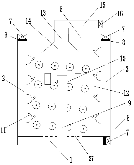
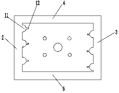
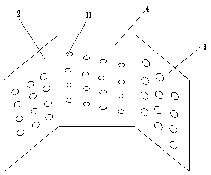
[0028] Such as Figure 1~3 As shown, a high heat dissipation electrical cabinet disclosed by the present invention includes an electrical cabinet body with a plurality of busbar terminals installed inside. The present invention mainly improves the structure of the electrical cabinet body and the structure of the busbar terminals. Improve the heat dissipation effect, but the installation position and installation form of the busbar terminal are not the protection content of the present invention, which can refer to the existing electrical cabinet, so it will not be described too much.

[0029] The electrical cabinet body has a bottom plate 1, a left side plate 2, a right side plate 3, a back plate 4, a top plate 5 and a front door 6, wherein the front door and the left side plate are h...


PUM


Abstract

The invention discloses a high heat-dissipation electrical cabinet comprising an electrical cabinet body. The electrical cabinet body is provided with a bottom plate, a left side plate, a right side plate, a back plate, a top plate and a front door, wherein the bottom plate and the top plate are double-layer hollow structure, while the back plate, the left side plate and the right side plate are double-layer hollow structure as well, and are communicated with each other. A first air inlet communicated with the interior is formed on one side face of the bottom plate. Meanwhile, the upper surface of the bottom plate is provided with an air outlet which is communicated with the air pipe and extends to the position of the inner female terminal of the cabinet body. Second air inlets are formedon the upper end surface of the left side plate and the right side plate, and a plurality of air outlet groups which are parallel to each other are provided on the inner wall of the back plate, the left side plate and the right side plate. Each air outlet group comprises a plurality of air outlets provided at intervals. The air outlets in the left side plate, the back plate and the right side plate are provided in a spiral manner. An exhaust port is formed on the top plate, wherein the upper surface of the exhaust port is communicated with the exhaust pipe, and the end of the exhaust pipe is provided with an air evacuating device. According to the high heat-dissipation electrical cabinet, a draught fan is utilized to fit a cabinet body of double-layer hollow structure.so that vortex airflow is formed in the electrical cabinet to dissipate heat in the interior, and the heat dissipation effect is improved.

Description

technical field [0001] The invention relates to an electric cabinet, in particular to a high heat dissipation electric cabinet. Background technique [0002] The electrical cabinet is a cabinet made of steel to protect the normal operation of components. Electrical cabinets are widely used in chemical industry, environmental protection industry, power system, metallurgical system, industry, nuclear power industry, fire safety monitoring, transportation industry, etc. When the electrical cabinet is working, the internal current exchange is easy to generate heat, especially the busbar is a component that is prone to heat, so the electrical cabinet with poor heat dissipation is likely to generate high temperature and cause accidents. [0003] The heat dissipation of the traditional electric control cabinet is mainly achieved by installing a cooling fan or an air conditioner on the surface of the electric control cabinet to achieve the heat dissipation of the electrical compone...

Claims


Application Information

Patent Timeline
IPC IPC(8): H02B1/56H02B1/20
CPCH02B1/207H02B1/565
Inventor 王强宋帅迪曹扬陈云张振娟朱海峰邓洁
Owner 义乌市谊诚信息科技有限公司
Why Eureka
Try Eureka